


Development Trend of Hydraulic Press
A hydraulic press is a type of mechanical equipment that uses liquid static pressure to process various materials. It is commonly used in pressing processes and forming processes, such as forging, stamping, cold extrusion, straightening, bending, flanging, sheet metal deep drawing, powder metallurgy, pressing, and so on. Since the invention of the first hydraulic press in 1795 to the present day, hydraulic presses have undergone over 200 years of improvement and innovation. Due to its versatility in various processes, hydraulic presses are widely used in various industries.
With the continuous development of modern manufacturing technology, the competition in the manufacturing industry is becoming increasingly fierce. In order to enhance the market competitiveness of hydraulic presses, traditional hydraulic presses must overcome the disadvantages of oil leakage, elevated oil temperature, low transmission accuracy, and high energy consumption. It is necessary to improve the control accuracy and efficiency of hydraulic presses, and achieve the design and manufacturing of green hydraulic presses.
The system and overall structure of hydraulic presses have become relatively mature after decades of development. Research on hydraulic presses at home and abroad mainly focuses on servo control technology, green energy-saving technology, integrated technology, hydraulic-fluid hybrid drive technology, multi-position hydraulic press technology, and other auxiliary technologies.
1. Servo Control Technology
Servo control is a precision driving technology that has developed over the past few decades. Its core technology is to ensure that the output of the object's position, orientation, status, and other parameters can follow the arbitrary changes in the input target (or set value). A servo hydraulic press is a new type of press that combines servo control technology with hydraulic systems. It refers to the main drive oil pump being driven by a servo motor, reducing the control valve circuit, and adjusting the main oil pump to achieve precise control of the slide.
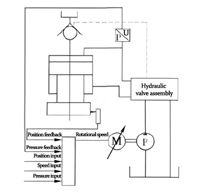
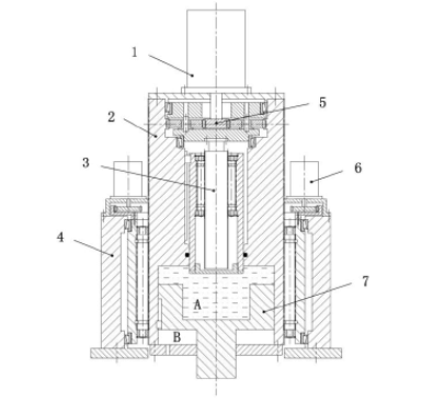
The figure above shows a servo hydraulic press cylinder. A pressure sensor is installed in the upper chamber of the main hydraulic cylinder of the hydraulic press, and a displacement sensor is installed at the slider of the hydraulic press. The controller calculates the speed of the servo motor based on pressure feedback signals, position feedback signals, pressure set signals, position set signals, speed set signals, etc., in order to control the output of the hydraulic pump for pressure, speed, and position control.
Servo-driven hydraulic presses rely on adjusting the speed of the servo motor to control parameters such as pressure, speed, and position of the hydraulic press, eliminating elements such as pressure control valves and flow control valves in the hydraulic control loop, thus simplifying the hydraulic control loop. During the fast descent and static upper limit position of the slider for loading and unloading, the servo motor speed is zero; during the pressing and return stroke of the slider, the servo motor speed is determined by the set speed; during pressure holding, the servo motor speed only compensates for leaks in the pump and system. In traditional hydraulic presses, the motor remains at a constant speed throughout the entire working process.
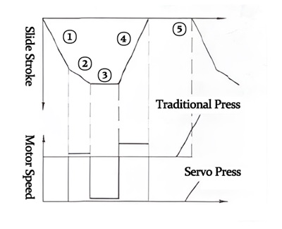
The figure above shows the difference in motor speed between traditional hydraulic presses and servo-controlled hydraulic presses throughout the entire working process. In the figure, 1 represents the fast descent stage of the slide, 2 represents the pressurization stage of the slide, 3 represents the holding pressure stage, 4 represents the return stage of the slide, and 5 represents the stage of loading and unloading when the slide is stationary.
Compared to traditional hydraulic presses, the application of servo control technology in hydraulic presses has the following advantages:
- High precision
Servo motors mainly rely on pulses for positioning, rotating the corresponding angle for each pulse received. Considering just the servo motor, its control precision can reach 1/1024 revolutions. Combined with corresponding sensors, precise control of the slide at any position can be achieved. The motion curve of a servo hydraulic press can be optimized compared to traditional hydraulic presses, and the appropriate slide curve can suppress rebound during the material pressing process, thus improving precision.
- High flexibility
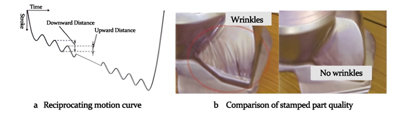
The slide motion curve can be optimized according to different production industries and molds, allowing for the design of special work characteristic curves for high difficulty and high precision processing, achieving "free movement" of the slide. The slide motion can be reciprocating, stopping at bottom dead center, and other complex motion modes. For example, as shown in Figure 3, Japanese scholars use a reciprocating motion curve to press thin sheet metal parts, effectively suppressing wrinkles at locations with large curvature deformation.
- High efficiency
The slider stroke number, slider speed, and stroke adjustment can be set within a large range, making it convenient to adjust according to the forming process. The slider can work with the minimum stroke, greatly improving production efficiency with the help of automatic feeding technology.
- Energy saving
Compared to servo hydraulic presses and mechanical presses, the need for flywheels and clutches is eliminated, and direct drive is used to greatly reduce transmission links. This results in reduced lubrication, strong maintainability, and no energy consumption due to clutch engagement. After the slider stops, the motor stops rotating, eliminating the energy consumption of motor and pulley idling. In conventional mechanical presses, flywheel idling consumes about 6% to 30% of the total energy consumption, while clutch (mainly referring to friction clutches) consumes about 20% of the total energy. Servo hydraulic presses do not have flywheels and clutches, thus saving this energy. A Japanese company once conducted a comparative test on the continuous power consumption of a 3000 kN hydraulic press, proving that servo hydraulic presses save energy by 32% to 42%.
Although servo control technology has shown strong vitality in hydraulic presses, there are still many key technologies that need to be improved:
A. Develop high-power servo motors and autonomous control units with independent intellectual property rights;
B. Develop hydraulic press main pumps driven directly by servo motors;
C. Research energy recovery systems;
D. Develop specialized control systems;
E. Develop an intelligent forming process library.
Currently, internationally renowned hydraulic component manufacturing companies such as Japan's NITTO SEIMO, Germany's Rexroth, Moog, and EATON VICKERS have developed AC servo hydraulic presses and formed product series. XIRO has also developed a series of servo hydraulic presses and introduced them to the market.
2. Green Energy-Saving Technology
Although hydraulic machines have advantages such as high energy density, versatility in processes, and low cost, issues such as high energy consumption, low energy efficiency, high noise levels, and environmental pollution from hydraulic oil leaks have been hindering their development. Green energy-saving technology aims to improve the energy efficiency of hydraulic machines and reduce hydraulic leaks, making it an important indicator for evaluating hydraulic machines. Green energy-saving technology will become an important direction for the future development of hydraulic machines.
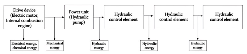
The energy transmission process in hydraulic systems is: electrical energy, chemical energy-mechanical energy-hydraulic energy-mechanical energy, as shown in the diagram.
Energy losses in hydraulic systems can be divided into three categories:
◆ Conversion losses of energy conversion elements.
This includes mechanical friction losses, pressure losses, and volumetric losses in hydraulic pumps and hydraulic motors. These energy losses mainly convert temperature rise into heat, and thermal energy is irreversible and cannot be recovered. The amount of energy loss is not only related to the type of energy conversion elements, but also factors such as operating conditions, operating points, and wear.
◆ Hydraulic circuit transmission losses.
Excess flow and excess pressure are the root causes of energy losses in hydraulic circuits. In hydraulic transmission systems, throttling control is the basic method to achieve various control functions, but unavoidable fluid resistance will create pressure drops, which inevitably result in energy losses. This energy is mainly transferred to the environment in the form of heat and cannot be recovered. These energy losses are mainly related to the hydraulic circuit.
◆ Matching losses caused by the mismatch between hydraulic sources and loads.
The tonnage of the hydraulic press is fixed at the design stage, but in different workpiece processing processes, there may often be situations where an oversized machine is used for a small task, resulting in the hydraulic source supplying more energy than needed, causing energy waste. Additionally, the effective working stroke of a hydraulic press is only about 1/3 of the total stroke or even smaller, resulting in energy waste during the idle stroke phase when the main cylinder is filled with high-pressure oil, which is also another important factor leading to temperature rise.
Based on the analysis, energy saving in hydraulic presses can be achieved by considering the following two aspects:
choose appropriate and efficient hydraulic components to improve and enhance energy conversion efficiency of components; and design a rational hydraulic system to improve and enhance the efficiency of the hydraulic system circuit.
Currently, research on green and energy-saving hydraulic presses at home and abroad mainly focuses on the following aspects:
1. Energy-saving hydraulic components
Energy-saving hydraulic components mainly focus on hydraulic pumps and hydraulic control valves. The world's four major hydraulic component manufacturers combine electronic control with variable hydraulic pump control to achieve good energy-saving effects, such as the servo control technology mentioned earlier. Meanwhile, the integration of hydraulic pumps with prime movers and the use of free-piston engines have the advantages of high efficiency and low noise, attracting attention from researchers at home and abroad. Hydraulic control valves mostly use throttling principles, causing pressure drop losses. However, control valves based on magneto-rheological fluids and electro-rheological fluids change the fluid viscosity using magnetic fields and electric fields to alter circuit pressure without pressure drop losses, significantly improving energy efficiency and providing new ideas for hydraulic energy-saving technology.
2. Energy-saving hydraulic systems
Japanese researcher Masao Egaki has classified the development of energy-saving hydraulic systems into five stages based on energy-saving effects, namely throttle valve control, load sensing valve control, load sensing pump control, pump displacement control, and pump speed control stages. The development trend is shifting from valve control to pump control.
The core idea of pump energy saving is to match the power provided by the hydraulic source with the load. Many energy-saving systems have emerged based on this idea, such as hybrid power technology, variable frequency speed regulation technology, hydraulic transformer technology, secondary regulation systems, and energy recovery systems. In the future, hydraulic energy-saving systems may be a fusion of advanced technologies, such as combining variable frequency speed regulation technology, energy recovery technology, and secondary regulation technology to achieve better energy-saving effects.
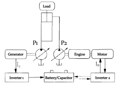
3. Hydraulic Transmission Technology
Hydraulic technology is actually an ancient technology that emerged during the first industrial revolution. It is the initial stage of hydraulic transmission technology. With the development of the petroleum industry, hydraulic oil replaced water as the working medium. As the call for energy conservation and environmental protection becomes louder in various countries around the world, many scientists have turned their attention to water as an environmentally friendly working medium.
The development and research of water hydraulic transmission technology from hydraulic transmission technology is not just a simple repetition and cycle of technology, but it aims to move towards a higher stage of development. Considering factors such as economy, environmental protection, fire resistance, compatibility with the working environment, and sustainable development, tap water (or seawater) is an ideal working medium.
Its main advantages are:
◆Low cost;
◆No pollution to the production products;
◆Good fire resistance;
◆Low compressibility.
However, in order to truly industrialize water hydraulic technology, key technologies such as anti-corrosion, cavitation, lubrication, and antifreeze must be solved, which brings challenges and opportunities to hydraulic machines.
3. Integrated Technology
1.Integration of Motor and Valve
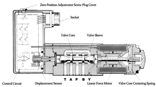
The electromagnetic direct drive valve is a new type of hydraulic valve that integrates the motor with a conventional hydraulic valve. As shown in the diagram below, the electromechanical transducer of this valve is a permanent magnet linear motor, used to directly drive the valve core. Compared to traditional servo valves, it eliminates the nozzle-shift stage and replaces the mechanical feedback device of the process load with advanced displacement sensors, simplifying the structure and improving reliability, greatly reducing manufacturing costs. This valve has been widely used in heavy industrial equipment such as die casting and metallurgy.
2. Motor and Pump Integration
Hydraulic motor pumps are a new type of hydraulic power component that integrates hydraulic pumps with prime movers. This structure of motor pump has advantages over the traditional motor-pump devices that are connected through couplings, such as compact structure, high power-to-weight ratio, small size, low noise and vibration, and high reliability. By integrating the motor internally, the overall size of the pump is reduced by 20%, and the working noise is reduced by more than 10dB. Both Voith Turbo H L Hydraulic of Germany and Daikin of Japan have series of products in this area, but there are fewer products domestically. The image below shows a axial piston hydraulic motor pump designed by Yanshan University. This structure integrates a permanent magnet synchronous motor with an axial piston pump, with the pump's inlet and outlet located at both ends of the pump body. The entire flow path surrounds the side wall of the pump body, allowing the heat generated by the motor stator, rotor, and various friction to be dissipated by circulating fluid flow inside the pump, serving as a cooling function.
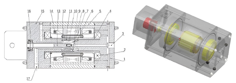
(1 front cover 2 large bearing 3 oil inlet 4 pump sleeve 5 housing 6 inclined plate 7 motor rotor 8 return plate 9 slide shoe 10 plunger 11 cylinder body 12 distribution plate 13 small shaft 14 motor stator 15 back cover 16 small bearing 17 oil return port)
4.Mechanical-hydraulic compound drive technology.
Designers and manufacturers of mechanical presses and hydraulic presses have long been debating the advantages and disadvantages of mechanical presses and hydraulic presses, expressing their own opinions. However, one undeniable fact is that both sides are continuously improving by absorbing each other's strengths and weaknesses. The hot topic in recent years has been the simultaneous application of hydraulic drive and mechanical drive on a press machine, with many similar patents both domestically and internationally. The diagram below shows a typical mechanical-hydraulic compound press.
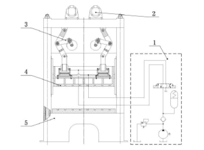
The blank stroke uses a servo motor to drive the crank connecting rod mechanism. When the connecting rod is completely vertical and in the locked state, the hydraulic system drives the cylinder to apply nominal force. The mechanical-hydraulic compound press separates the blank stroke from the nominal force stroke, with the blank stroke driven by a servo motor. This effectively reduces the waste of hydraulic energy during the blank stroke phase, while maximizing the advantages of rapid and precise positioning of mechanical presses. The servo motor for the blank stroke is used to improve control accuracy.The following illustration shows separate driving for the freewheeling stroke and work stroke cylinders.
(1 large motor 2 inner cylinder body 3 planetary screw 4 outer cylinder body 5 planetary reducer 6 small motor 7 piston rod)
Based on the principle of separate driving for idle stroke and working stroke, many energy-saving hydraulic cylinders can be designed. The image above shows a boosting cylinder that combines a planetary screw and a servo motor. The idle stroke is driven by a low-power motor, while the working stroke is driven by a high-power motor in conjunction with a planetary gear reducer and a boosting chamber. The overall structural design is clever and compact.
Both domestic and foreign countries have done a lot of work in recent years on mechanical-hydraulic composite drive, with research results from Germany and Japan being representative. Although the design schemes of the two countries are different - Germany uses mechanical transmission (such as crankshaft connecting rod system) as the main drive of the press, while Japan uses hydraulic systems as the main drive - the basic aim of both modes is to combine the advantages of mechanical presses and hydraulic presses in one machine. Many companies (including well-known large enterprises) and research institutions have invested a lot of manpower and financial resources in this area, which in itself reflects the importance of this research and development project. Practical prototypes have been developed, but they still need to undergo various tests and continuous improvements for some time. It is believed that in the foreseeable future, these new types of presses will have products available in the market to meet user needs.
5. Multi-station hydraulic press technology
For example, in the production process of automotive body panels and structural components, multiple stamping processes such as punching, flanging, shaping, and hole punching are required. For some high-strength steel plates, hot forming is also required. Previously, single-station pressure equipment was used to sequentially complete each process. Due to the dispersed layout of the equipment, the workpieces need to be transported in between, which reduces production efficiency, increases floor space, and for hot forming workpieces, secondary heating is required, wasting energy.
Multi-station press is an advanced press equipment, integrating multiple presses, generally consisting of line head unit, feeding mechanism, press, and line tail section. The fastest cycle rate can reach more than 25 cycles per minute, meeting the requirements of high-speed automated production of multi-station hydraulic press structure, as shown in the diagram below. It adopts an integral welded frame structure, with multiple hydraulic cylinders arranged in an orderly manner, coordinated with automatic feeding technology. Uploading and unloading can quickly complete the stamping manufacturing process from blank to finished product.
Multi-station hydraulic press has the following advantages:
a. Multiple processes are completed in different stations in one hydraulic press, reducing the number of hydraulic presses and thereby reducing the equipment floor space;
b. Reducing the feeding procedures and operators in between the equipment;
c. Improving production efficiency;
d. Reducing investment costs.
6. Other auxiliary technologies
1. Automatic feeding technology
Automatic feeding technology mainly serves multi-station hydraulic presses, using multi-axis articulated robots to quickly pick up workpieces, flip them, and accurately place them in the next process.
Automatic feeding is one of the basic conditions for automatic production lines. Due to the different dimensions, shapes, structures, and physical properties of materials of the products, there are many types of automatic feeding mechanisms.
According to the different control methods of the feeding mechanism, they can generally be divided into: mechanical, electrical, hydraulic and pneumatic, and combination. Generally, feeding mechanisms are designed separately based on a specific condition, with poor versatility, requiring specialized technical personnel for design and maintenance. With the development of robotic technology, multi-degree-of-freedom mechanical hands based on human joint studies have rapidly developed, with strong versatility, high control precision, and can achieve a very high level of automation when combined with image processing technology, essentially achieving unmanned operation.
The diagram shows the freedom assembly robot developed by Epson. It can quickly transfer workpieces between different processes, achieve intelligent manufacturing with image processing technology, such as detecting part quality and defects.

2. Intelligent Blankholder Deep Drawing Technology
A blankholder is an auxiliary component of a hydraulic press, providing appropriate edge pressure to the sheet metal during the deep drawing process. In traditional deep drawing processes, blankholders generally use hydraulic or pneumatic methods, with constant edge pressure throughout the deep drawing process. This method can meet the requirements for simple and shallow deep drawing workpieces, but for workpieces with complex internal structures or asymmetrical parts, constant edge pressure is no longer sufficient for deep drawing requirements. Therefore, intelligent blankholder deep drawing technology has emerged to address this issue.

The continuous development of CNC technology has led to the emergence of CNC hydraulic cushion, which can real-time control the flanging force according to the sheet forming process requirements, that is, the flanging force at each point can be set to different values and can be controlled in segments. The upper figure (left) shows the zone-variable flanging force deep drawing cushion device developed by Schuler Company, which can meet the deep drawing forming of complex parts. The upper figure (right) shows a hydraulic-driven multipoint variable-pressure deep drawing cushion, which can arrange the flanging force process according to the deep drawing characteristics of the workpiece. This type of deep drawing cushion can effectively control the size of the flanging force during the deep drawing stroke, ensuring the processing quality of the workpiece.

(1. Nut 2. Lead screw 3. Ejector rod 4. Servo motor 5. Brake)
With the development of servo motor technology, electric deep drawing equipment driven by servo motors features high efficiency, high precision, intelligence, and green environmental protection. The figure above shows an electric servo deep drawing equipment, where servo motor 4 drives the screw rod 2 through a synchronous belt, and nut 1 converts the rotation motion of the screw into the up and down motion of the top die. By eliminating the intermediate transmission link, the control accuracy and transmission efficiency are greatly improved. Compared to hydraulic and pneumatic cushions, electric servo deep drawing equipment has higher controllability, smaller space requirements, and the advantages of green environmental protection and energy saving.
Conclusion
From the analysis above, it can be seen that intelligence and green energy conservation are the two major development themes of future hydraulic presses. The combination of servo drive technology with hydraulic pumps, hydraulic valves, and deep drawing cushions improves the control accuracy and response speed of hydraulic presses, reduces costs and energy consumption. The application of new hydraulic devices, water hydraulic technology, energy-saving hydraulic systems, integrated technology, and mechanical-hydraulic hybrid drive technology will help traditional hydraulic technology overcome its high energy consumption disadvantages and move towards green energy conservation. The development of modern hydraulic technology no longer solely relies on the hydraulic industry itself but involves the collaborative development of multiple disciplines. The future development of hydraulic presses will depend more on the integration of technologies from various disciplines such as materials science, electrical engineering, and control engineering, injecting new vitality into traditional hydraulic technology.

XIRO-electric servo press/XIRO-hydraulic press/XIRO-mechanical powder compacting press
XIRO, an automated machine manufacturer, 24-hour response factory, with a professional engineering team 24 hours online technical service. All machines are CE certified, come with a 2-year warranty, and lifetime service. With 20+ years rich production experience, our equipment is exported to more than 60 countries. We provide customizable press machines and comprehensive productivity solutions, ensuring it's the most competitive, accurate solution to any assembly requirement! XIRO wishing you prosperity!

|

|

|


