


 +86 15913754357
 sales@xirotech.cn
 Release time:2023.11.01
In modern industrial production, hydraulic presses are widely used in various fields of mechanical production processes such as metal forming, stretching, twisting, and extrusion. In recent years, in order to improve the efficiency of mechanical processing production in China, it is very necessary to develop high-performance hydraulic presses, with synchronous control systems being a key technical issue.
Researchers have designed a hydraulic system that can achieve displacement synchronization for a double-cylinder four-column hydraulic press based on the functional requirements for displacement synchronization control. They used AMESim and Simulink software to model the double-cylinder synchronous hydraulic system. Researchers also compared and analyzed the dynamic effects of fractional-order PID and conventional PID on hydraulic cylinder motion control, verifying that the designed fractional-order PID controller has good performance.
1. Double-cylinder four-column hydraulic press displacement synchronization control system
1.1 Control system design and structural analysis
According to the actual control requirements of the double-cylinder four-column hydraulic press displacement synchronization control system, a closed-loop synchronous control system is designed as follows: the system uses position feedback control, where the controller collects real-time positions of the hydraulic cylinders through displacement sensors and compares them with the specified positions to generate an error. This error, after being processed by the controller, is converted into current for the servo proportional valve, which then controls the output hydraulic energy of the servo proportional valve to reduce deviations of the hydraulic cylinders. The controller applies fractional-order PID control, and the system control diagram is shown in Figure 1.
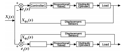
Figure 1. Diagram of double-cylinder four-column hydraulic press displacement synchronization control system
1.2 Establishment of the system's mathematical model
Based on the diagram of the double-cylinder four-column hydraulic press displacement synchronization control system, the system's transfer function is established.
1.2.1 Construction of the hydraulic cylinder mathematical model
The transfer function of the hydraulic cylinder piston displacement to input flow rate is given by:
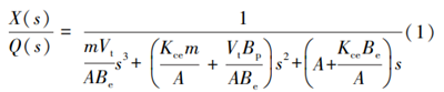
Equation: X represents the displacement of the cylinder rod; A is the effective area of the piston; Kce is the leakage coefficient; Vt is the volume of hydraulic oil in the high-pressure chamber of the hydraulic cylinder; Be is the elastic modulus of the hydraulic oil volume; Bp is the viscous damping coefficient.
1.2.2 Construction of mathematical model for servo proportional valve
The transfer function of the servo proportional valve is commonly approximated using an oscillation element, that is:
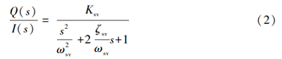
In the equation: Ksv is the flow gain of the electro-hydraulic servo valve; ωsv is the natural frequency of the electro-hydraulic servo SV valve; ζsv is the damping ratio of the electro-hydraulic servo valve.
1.3 Design of Displacement Synchronized Hydraulic System for Double-cylinder Four-column Hydraulic Press
According to the overall design requirements of the double-cylinder four-column hydraulic press, the hydraulic system designed adopts a quantitative closed-loop circuit. The executive components of this hydraulic system consist of 2 double-acting hydraulic cylinders, each of which is independently controlled by a corresponding servo proportional valve. In order to adjust the hydraulic press to the specified position and quickly lock it to maintain position accuracy, this system uses a hydraulic lock; in order to unload the hydraulic pump when the hydraulic press is idle or stopped, the system uses a proportional relief valve. According to the design parameters and performance requirements, the maximum stroke of the hydraulic cylinder can be calculated to be 1m. The main parameters of the hydraulic system are shown in Table 1. According to the design requirements mentioned above, the designed hydraulic system is shown in Figure 2.
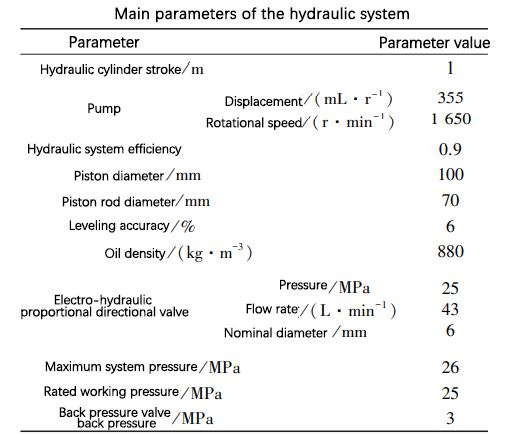
Table 1
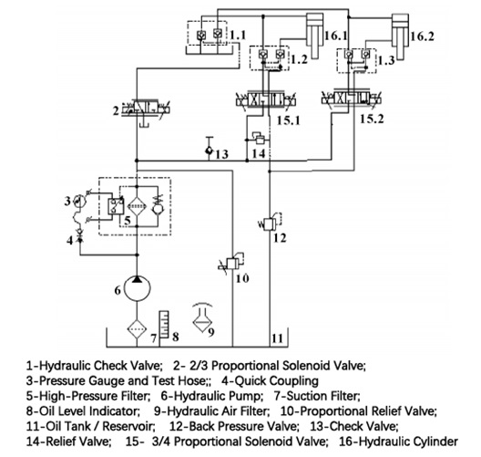
Figure 2: Hydraulic leveling system schematic diagram
The specific working principle of the dual-cylinder four-column hydraulic press displacement synchronous control hydraulic system is as follows: At the beginning, the moving crossbeam is in the original position, with the hydraulic cylinder rod not extended. Start the hydraulic press, which enters the downward working state. The displacement sensor collects the displacement data of the hydraulic cylinder and sends the data to the controller. The controller compares the real-time position of the hydraulic cylinder collected by the displacement sensor with the specified position, sends out a control signal, the hydraulic pump 6 starts working, and the three-position four-way proportional solenoid valve 15 is switched to the right position. Hydraulic oil passes through the suction oil filter 7, hydraulic pump 6, and reaches the high-pressure filter 5; when the hydraulic pressure output by the gear pump 6 reaches a certain value, the hydraulic oil enters the three-position four-way proportional solenoid valve 15 on the right side through the high-pressure filter 5, and the hydraulic cylinder 16 starts to extend outward. The hydraulic cylinder 16 is equipped with a displacement sensor, which collects the actual displacement signal of the hydraulic cylinder rod and compares it with the ideal displacement signal. When the displacement deviation is within the error range, the proportional solenoid valve 15 is in the middle position, stops the oil supply, and ends the downward movement. Due to the hydraulic lock formed by the hydraulic control check valve group 1.2 and 1.3, the hydraulic cylinder 16 can be locked in the set position. The speed of the hydraulic cylinder extension or return journey can be adjusted by adjusting the servo proportional valve 15. When the hydraulic cylinder returns, because the pressure in the rodless cavity of the hydraulic cylinder is high, the two-position three-way proportional solenoid valve 2 on the right side needs to be switched first. The high-pressure oil in the rodless cavity of the hydraulic cylinder flows back to the tank through the hydraulic control check valve. After a period of time, the unloading is completed, and the two-position three-way proportional solenoid valve 2 returns to its original position. Finally, the proportional solenoid valve 15 on the left side is switched on until the hydraulic cylinder returns. A back pressure valve is installed on the return oil path to generate a certain amount of back pressure resistance, improving the smooth movement of the hydraulic cylinder. When the position of the hydraulic cylinder 16 is locked, the proportional overflow valve 10 can be adjusted to unload the hydraulic pump.
2. Fractional Order PID Controller
The structure diagram of the fractional order PID control system is shown in Figure 3.
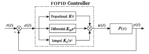
Figure 3: Structure diagram of the fractional order FOPID control system
The transfer function of the fractional order PID controller is as follows:
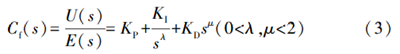
In the formula: U(s) is the output of the controller; E(s) is the error input of the controller. Compared with traditional integer-order PID controllers, fraction-order controller PID not only has three degrees of freedom, KP, KI, and KD, but also adds two more degrees of freedom, λ and μ, thus having a greater range of adjustment.
By choosing reasonable parameters, fraction-order PID controllers will play a significant role in improving system flexibility, robustness, and overall control performance, achieving better control effects. Moreover, fraction-order PID controllers have the characteristic of "infinite memory", using fractional differential equations to describe the dynamic characteristics of the system more comprehensively and accurately. The conventional PID controller is just a special case of the fraction-order PID controller, therefore, fraction-order PID controllers have all the excellent performance of conventional PID controllers.
3. Simulation and analysis of displacement synchronous hydraulic system of double-cylinder four-column hydraulic press
3.1 AMESim simulation model of synchronous hydraulic system
Based on the working principle of the displacement synchronous hydraulic system of a double-cylinder four-column hydraulic press mentioned above, the model is simplified under the condition of meeting requirements. The system adopts the method of hydraulic cylinder position feedback, with displacement sensors installed on each hydraulic cylinder to collect displacement data. The data collected is processed by a fraction-order PID controller, and the processed data is then applied to the servo proportional valve to control the output hydraulic energy of the servo proportional valve, thereby controlling the movement of the hydraulic cylinder rod and achieving the synchronous requirements of the double cylinders. Select corresponding components from the hydraulic, mechanical, and signal libraries in AMESim to build the simulation model as shown in Figure 4. The main parameters of the simulation model are shown in Table 1.
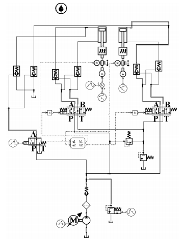
Figure 4 Simulation Model of Displacement Synchronized Hydraulic System of Double Cylinder Four Column Hydraulic Press
3.2 Synchronous hydraulic system Simulink control model
According to the fractional-order FOPID control system structure diagram, the fractional-order PID control module is constructed in Simulink as shown in Figure 5. According to the displacement synchronous control system diagram of dual-cylinder four-column hydraulic press, using the internal interface of AMESim and Simulink software, the joint simulation of AMESim hydraulic system model and Simulink control system model is realized, and the system control diagram is constructed as shown in Figure 6.
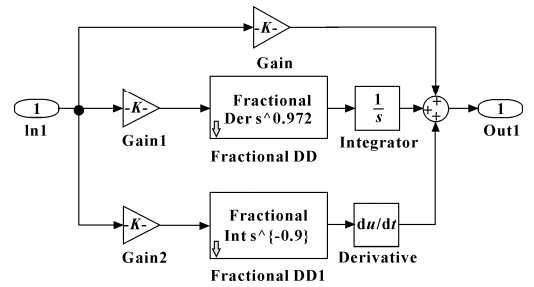
Figure 5 Fractional-order PID controller
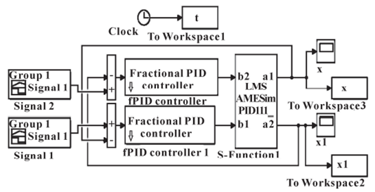
Figure 6 System Simulink simulation model
3.3 Synchronous Hydraulic System Analysis
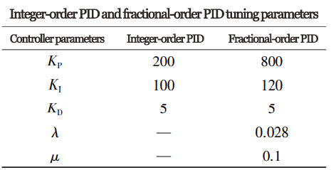
In order to facilitate the analysis of the performance of fractional-order PID control, a comparison method with conventional PID is adopted. The specific setting parameters of integer-order PID and fractional-order PID are shown in Table 2. Figure 7 shows the ideal displacement and actual displacement curves of the hydraulic cylinder under FOPID control, while Figure 8 shows the same curves under conventional PID control. Figure 9 shows the difference curve between ideal displacement and actual displacement under FOPID control, and Figure 10 shows the same under conventional PID control. Figure 11 shows the actual movement speed curve of the hydraulic cylinder rod under FOPID control, and Figure 12 shows the same under conventional PID control.
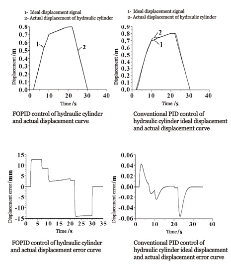
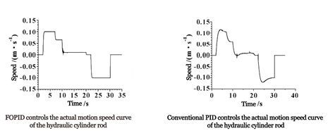
Figures 7 and 9 show that when using FOPID control method, the actual displacement curve of the hydraulic cylinder follows the ideal displacement signal more closely. From Figure 9, it can be seen that during the operation of the hydraulic machine, the maximum difference between the actual displacement and ideal displacement of the hydraulic cylinder is 0.01264834m, within the allowable error range. Figures 8 and 10 indicate that using conventional PID control results in certain fluctuations during the operation of the hydraulic machine. From Figure 10, it can be seen that during the operation of the hydraulic machine, the maximum difference between the actual displacement and ideal displacement of the hydraulic cylinder is 0.05558151m. By comparing the control effects of the two different controllers, it is evident that the FOPID control effect is superior to conventional PID control. Therefore, using FOPID will greatly improve the system's precision. According to the working conditions of the hydraulic machine, a constant force of 1000N is applied on the hydraulic cylinder from t=12~18s. Comparing Figures 11 and 12, it can be seen that during this time period, the speed fluctuation of the hydraulic cylinder under FOPID control is smaller. Therefore, fractional-order FOPID can better ensure system stability and has good robustness.
4. Conclusion
In response to the functional requirements of synchronous displacement control of a dual-cylinder four-column hydraulic press, a hydraulic system capable of achieving synchronous displacement control of a dual-cylinder four-column hydraulic press is proposed and designed. Using Simulink for modeling, a comparative analysis of the dynamic effects of fractional-order PID and conventional PID on the motion control of hydraulic cylinders was conducted. The following conclusions were drawn through simulation analysis:
1. The fractional-order PID controller has better dynamic performance than the integer-order PID controller. Additionally, the fractional-order PID controller has stronger robustness, ensuring system stability better when the parameters of the hydraulic system for synchronous displacement control of a dual-cylinder four-column hydraulic press change.
2. The fractional-order PID controller has high control accuracy for the synchronous hydraulic system of dual cylinders, overcoming the shortcomings of conventional PID control and achieving the design goals and requirements of synchronous displacement control of a dual-cylinder four-column hydraulic press. Through comparing the digital implementations of conventional PID controllers and fractional-order PID controllers, it is demonstrated that the fractional-order PID controller is operationally feasible in process control, providing a reference for the design of hydraulic machine controllers in the future.
XIRO-electric servo press/XIRO-hydraulic press/XIRO-mechanical powder compacting press
XIRO, an automated machine manufacturer, 24-hour response factory, with a professional engineering team 24 hours online technical service. All machines are CE certified, come with a 2-year warranty, and lifetime service. With 20+ years rich production experience, our equipment is exported to more than 60 countries. We provide customizable press machines and comprehensive productivity solutions, ensuring it's the most competitive, accurate solution to any assembly requirement! XIRO wishing you prosperity!


