


 +86 15913754357
 sales@xirotech.cn
 Release time:2023.01.01
The law of metal plastic deformation directly affects the organization performance of materials, which in turn affects the quality of the product. Among a large number of forming curves, forming metal parts according to the harmonic law results in the deformation speed and acceleration changing periodically in a harmonic cycle. On one hand, this can reduce system pressure impact, making the press machine work smoothly. On the other hand, it is conducive to strengthening the organizational performance of materials, improving the forming quality of metal.
Due to its high power-to-mass ratio, forming systems generally use hydraulic drive. However, the nonlinearity and uncertainty of hydraulic systems make it very difficult to achieve high-performance tracking, thereby affecting the formability of materials. Researchers have proposed a large number of advanced PID control strategies and nonlinear control strategies for hydraulic systems, such as fuzzy PID control, feedback linearization control, variable structure control, robust control, and neural network control. Although these strategies can improve the dynamic characteristics of hydraulic systems, they are generally used to improve the response characteristics of step signals, lacking targeted tracking of periodic position signals and lacking solutions for lag and errors during the tracking process.
For systems that undergo periodic motion, using learning strategies such as iterative learning control, repetitive control, and batch control can effectively improve system performance. Among them, repetitive control strategies have strong advantages in dealing with single-input, single-output model systems, which just happen to be the model of hydraulic position control systems.
Therefore, this paper takes the hydraulic metal forming system as the research object. Firstly, an experimental platform simulating metal forming is constructed in the laboratory, and a composite control strategy (ROF) based on repetitive control and output feedback control strategies is proposed to improve the periodic signal tracking characteristics of the hydraulic press.
Specific arrangements are as follows: first, describe the hydraulic metal forming system, then establish the mathematical model of the forming system; secondly, based on the composite control strategy, study the position tracking characteristics of the system, compare and analyze it with PID control, and finally draw conclusions.
1. Description of the forming system
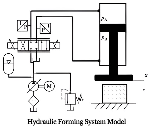
The schematic diagram of the hydraulic press metal forming system is as shown in Figure 1, where PA and PB are the pressures of the two chambers, x is the displacement of the hydraulic cylinder. The hydraulic pump provides the required flow rate for the system, and the electro-hydraulic servo valve controls the extension and retraction of the hydraulic cylinder. The piston rod of the hydraulic cylinder is hinged to the movable beam, and the workpiece is placed between the movable beam and the worktable. The periodic rise and fall of the movable beam achieve batch rapid forming of the workpiece.
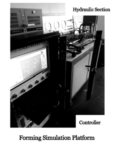
In order to simulate hydraulic forming, a metal forming process simulation experimental platform was established, as shown in Figure below. The platform includes three parts: host computer (including Labview software), industrial computer, and hydraulic system. The hydraulic system mainly consists of a drive system and a load system, and uses two hydraulic cylinders to connect the two systems in a head-to-head manner. The load system is used to simulate the deformation resistance of metal and other external loads.
2. System mathematical model
(1) Hydraulic drive model
Assuming that the servo valve spool parameters are consistent, that is, the asymmetry of the valve is not considered, and the influence of the overlap amount of the servo is ignored. The force balance equation of the hydraulic cylinder load can be expressed as:

Where: x, ẋ, and ẍ are the displacement, velocity, and acceleration of the hydraulic cylinder respectively; m is the load mass; AA and AB are the areas of action of the two chambers; B is the viscous damping coefficient; Fr is the resistance force of metal deformation; Ff is the friction force at the sealing and guiding positions.
The flow entering chambers A and B of the hydraulic cylinder can be respectively represented as:
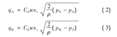
Where: qA and qB are the flows entering chambers A and B of the hydraulic cylinder; PS and PT are the supply pressure and tank pressure of the hydraulic pump respectively, and the pressure in the tank is generally set to 0; Cd is the valve coefficient; w is the valve window area function; xV is the valve core displacement; ρ is the density of the fluid medium.
Ignoring the external leakage of the hydraulic cylinder, the continuity equation for the flow of the hydraulic cylinder is:
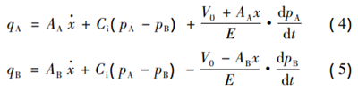
In the equation: V0 is the initial hydraulic volume containing the pipeline and hydraulic cylinder; E and Ci are the volume modulus and leakage coefficient of the hydraulic oil respectively. If the time-varying characteristics of the parameters are not considered, they are generally set as constants; t is time.
After the hydraulic valve is selected, the rated flow and rated pressure are usually provided without specifying the parameters of the valve aperture. Therefore, in engineering, the coefficient Bv is defined to characterize the valve aperture flow parameters, and its expression is:
.png")
In the equation: QN and PN are the rated flow and rated pressure of the servo valve respectively; umax is the rated output voltage.
(2) Load force model
The load force includes metal deformation resistance and frictional force. In particular, the metal deformation resistance Fr is related to many factors, mainly including the degree of deformation, deformation speed, deformation acceleration, deformation temperature, and material properties. For periodically varying metal resistance, it can be described as:
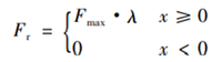
In the equation: Fmax is the peak value of deformation resistance; λ is a periodic function, ‖λ‖ < x<1, meaning that the deformation resistance is a bounded function.
For hydraulic machines, there are generally friction forces from guide columns and seals, and the friction force Ff can be approximated as:
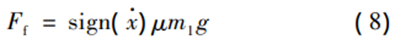
In the equation: μ is the equivalent friction coefficient; m1 is the mass of the moving part; g is the acceleration due to gravity.
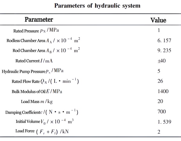
In actual forming processes, it is difficult to measure deformation resistance and friction force in real-time. Therefore, constant values with disturbance values are used to simulate deformation resistance and friction force in hydraulic experimental systems. However, due to the difficulty in precisely tracking the required load force in the platform's load system, the load can also be considered as a constant value with disturbance values, which is in line with the uncertainty of the load conditions in the forming process. The parameters of the entire hydraulic system are shown in Table 1.
3. Control Strategy
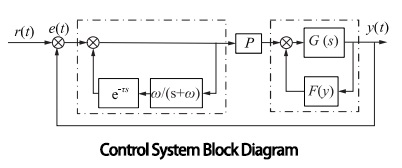
The system timing control process diagram is shown in Figure below, which includes 3 parts. In this diagram, r(t) is the system input, e(t) is the error, w/(s+w) is the filtering function, and y(t) is the system output. The first part involves output feedback on model G(s), with the feedback function as F(y), used to change the location of the system poles and enhance stability. The second part is the repetitive controller e-Ts (where T is the period time constant, s is the frequency, and e is the natural constant), used to eliminate periodic errors. The third part is proportional control P, to improve response speed and reduce steady-state errors. Since the hydraulic system is a regular system, a low-pass filter is added before the repetitive controller term, with a cutoff frequency of w.
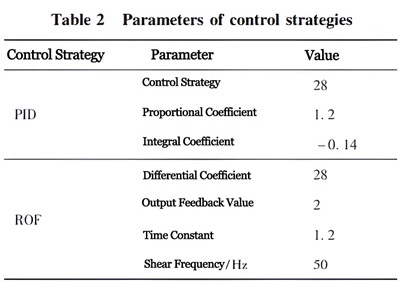
The control system is programmed using Labview and executed on an industrial computer, with a sampling time of 5 ms, and the load force set at 2 kN. The control parameters of the system are shown in Table 2.
4. Results Analysis
The application effects of control strategies were tested on the experimental platform, as shown in Figures below. The iamge compare the tracking of periodic displacement signals under PID control and ROF control strategies. The reference signal is a harmonic function with an amplitude of 10mm and a period of 1 second, with a 0.2-second waiting time set between each working period.
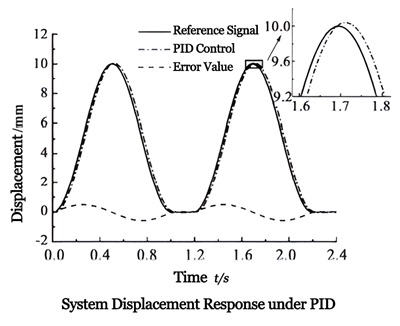
The upper graph shows the response characteristics of the system under PID control for 2 periods. It can be seen that with PID control, there is a lag of about 0.05 seconds in the tracking process, and the tracking error varies periodically, with a maximum error of 0.5mm and a period of 1.2 seconds, matching the reference signal period.
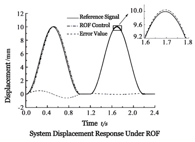
The upper graph shows the system response characteristics under ROF control for 2 periods. It can be observed that with ROF control, after completing one period, there is almost no lag in the tracking process, and the tracking error tends to stabilize, with a maximum of 0.05mm and a response curve period of 1.2 seconds, matching the reference signal period.
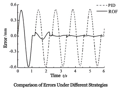
The upper graph compares the tracking error under the two strategies. Using ROF control, the tracking error of the system after 2 periods increased from 0.5mm to 0.05mm, indicating that ROF control can improve the tracking accuracy of the system.
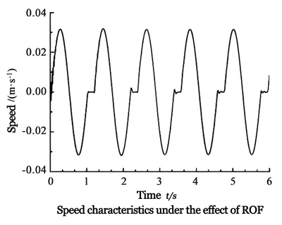
The upper graph shows the velocity characteristics curve under ROF control. It can be seen that the velocity during the forming process is basically a harmonic curve, with a period of 1.2 seconds, an amplitude of 0.03 m·s-1, only fluctuating slightly near the starting position, indicating the ability to achieve periodic forming velocity.
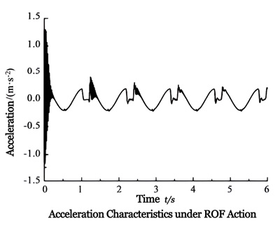
The upper graph is the acceleration signal under the ROF strategy. In the first period, especially at the moment of system startup, the acceleration fluctuates greatly, then stabilizes, with a maximum acceleration of 0.2m·s-2. Regardless of the system's state, the system acceleration remains bounded, indicating minimal impact and good stability in the system's motion.
5. Conclusion
(1) The use of PID control results in periodic errors with an error magnitude of 0.5mm and lag in the tracking process.
(2) ROF control strategy can effectively track periodic signals. The tracking error is less than 0.05mm, ensuring the quality of forming, and the forming velocity signal is approximately periodic, which can improve the structural performance of metal forming parts. The acceleration signal fluctuates within a limited range, reducing system impact and improving the smoothness of system motion.


XIRO-electric servo press/XIRO-hydraulic press/XIRO-mechanical powder compacting press
XIRO, an automated machine manufacturer, 24-hour response factory, with a professional engineering team 24 hours online technical service. All machines are CE certified, come with a 2-year warranty, and lifetime service. With 20+ years rich production experience, our equipment is exported to more than 60 countries. We provide customizable press machines and comprehensive productivity solutions, ensuring it's the most competitive, accurate solution to any assembly requirement! XIRO wishing you prosperity!
 |  |  |

