


Inventory of energy-saving technologies of hydraulic press hydraulic systems
Hydraulic press hydraulic systems are characterized by high installed power, high working pressure, large flow rate, and high frequency. In recent years, research on energy-saving technologies for hydraulic presses has been increasingly emphasized, and green energy conservation is also one of the development trends of hydraulic presses.
The energy consumption of hydraulic press hydraulic systems mainly manifests in the increase of oil temperature in the hydraulic system. The harm is to increase the internal leakage and external leakage of hydraulic components, accelerate the aging of the oil, causing the oil to lose its original lubricity, viscosity-temperature characteristics, and other physical properties, accelerate the wear and performance reduction of components in the hydraulic system, affect the lifespan and reliability of components, and result in a decrease in equipment efficiency or even loss of function. In addition, due to the heating of the hydraulic system, a cooling system needs to be installed to dissipate the heat generated by the hydraulic system, and the cooling system also requires a certain power consumption, further increasing the energy consumption of the hydraulic system and the consumption of cooling water resources.
So how can hydraulic presses be energy-saving and environmentally friendly? First, energy consumption needs to be analyzed, and then targeted measures can be taken to achieve the best results.
Energy Consumption Analysis
The energy consumption of hydraulic press hydraulic systems can mainly be divided into two categories:
1. Hydraulic system energy consumption refers to the energy consumption of hydraulic components and systems, such as internal leakage, external leakage, pressure loss, pipeline loss, overflow, throttling, etc. Especially the power loss caused by unreasonable system design and component configuration.
2. Press motion energy consumption refers to the energy consumption generated by mechanical actions that do not do work on the workpiece, such as the rapid descent of the hydraulic press slider, causing the potential energy of the slider to be converted into thermal energy consumption without contributing to the forming of the workpiece.
Methods to reduce the energy consumption of hydraulic systems
1. Choose volume control as much as possible
Use a combination of multiple pumps' flow rates
Using a combination of multiple pumps' flow rates to achieve volume control. This method is a relatively ideal energy-saving method, but the disadvantage is that it requires more pumps and valves, resulting in a larger and more costly system that cannot achieve stepless speed regulation. This speed control scheme is more commonly used in larger systems.Use variable pump speed control
Variable pump speed control is an ideal speed control method that can effectively reduce energy consumption. Various forms of variable pumps such as hydraulic control variable pumps, constant power variable pumps, load-sensitive variable pumps, electro-hydraulic servo variable pumps, digital variable pumps, electric variable pumps, electro-hydraulic proportional variable pumps, electro-hydraulic servo variable pumps, and servo motor-driven variable pumps can be selected to achieve volume control. The hydraulic pump provides the system with the amount of flow required by the actuator, eliminating excess flow loss.In systems that require pressure holding, the characteristics of some pumps can be utilized to output very small flow rates to supplement system leaks in order to maintain pressure. For presses with high pressure holding requirements, a closed-loop pressure control system can be achieved by using a hydraulic oil source driven by a servo motor and a pressure sensor on the main cylinder, which can achieve high pressure control accuracy and low energy consumption.
2. Choosing Hydraulic Valves Reasonably
Currently, hydraulic valves can mainly be divided into three categories based on their structure: conventional sliding valve type, threaded cartridge valve type, and two-way cartridge valve type. Installation forms can be divided into plate connection, pipe connection, stacked connection, and cartridge connection.
Conventional sliding valve types often have large clearances between valve cores, limited by their structure, with relatively short sealing lengths and complex internal flow paths. Therefore, the leakage and internal pressure loss of these valves are relatively large, making them suitable for low pressure and small flow rate applications.
Cartridge valve types have a relatively simple structure with high integration. Besides valve body functions, the hydraulic block also serves as the system's flow path, eliminating the need for pipes between valves. This results in significantly less pressure loss within the valve compared to sliding valve components. They utilize a conical seal structure at the valve port, which generally achieves leak-free performance. The sliding parts have longer sealing lengths, and with good control over the clearance between the valve sleeve and the valve core, leakage is minimal. In terms of internal leakage, cartridge valves have a significant advantage over conventional sliding valves. Therefore, when designing hydraulic systems for hydraulic machinery, you should try to use cartridge valves as much as possible. It's important to note that threaded cartridge valves have poor flow capacity and significant pressure loss due to their size and structural limitations, making them suitable for mobile machinery and only suitable for use in small hydraulic machines.
3. Optimizing System Design
Proper selection of hydraulic valve specifications
Calculate the flow rate required for each action of the hydraulic machine, clarify the maximum flow rate that each hydraulic valve actually passes through when the press is in action, and select the valve specifications based on the flow rate passed by each valve.If the valve specifications are chosen too small, it will increase pressure loss in the components, causing the hydraulic oil to heat up and consume energy. The selection of valve specifications can be based on the parameters provided in the product samples of each manufacturer, or selected based on empirical methods. Generally, the specifications of the valve can be determined based on the pipe diameter, with the valve diameter being one size smaller than the pipe diameter. It is important to note that when using a piston cylinder, the maximum oil discharge flow in the rodless chamber occurs when the piston rod retracts, and the valve specifications should be determined based on this discharge volume.
Correctly design hydraulic blocks
After determining the valve specifications, in possible situations, try to increase the internal aperture of the hydraulic block to reduce flow rate; when the holes inside the hydraulic block are matched, control the drilling depth well to prevent dead angles and vortex formation, which can cause pressure loss.
When using two-way cartridge valves, calculate the flow velocity of the annular flow channel between the valve sleeve and the cartridge hole to avoid high flow rates causing excessive flow resistance leading to the hydraulic oil heating up or causing slow cylinder movement. The recommended flow velocity inside the hydraulic block is: ≤ 6m/s for high-pressure flow channels, and ≤ 3m/s for low-pressure flow channels.Optimization of pipeline design
Try to shorten pipelines, use flange connections instead of threaded pipe fittings, as flange connections generally do not have sudden expansions or contractions in the flow path, and the connection reliability is very good, making it less likely to loosen. Conversely, threaded connections always have flow path change issues, which can cause unnecessary pressure loss, lower reliability, and frequent occurrences of loosening and oil leakage.Properly select the inner diameter of the pipes. The flow velocity inside the pipes should not be too high, with the flow velocity in low-pressure pipelines generally controlled below 3m/s, and in high-pressure pipelines controlled below 6m/s. The flow velocity in the pump suction pipe should not exceed 1.5m/s, while the flow velocity in the return oil pipeline should be below 1.5-3m/s.
Pipelines should minimize right-angle bends, sudden expansions or contractions in the cross-sections; the bending radius should not be too small, ideally maintained at 5 times the pipe diameter or more. Avoid folds and narrowing at pipeline bends.
Select the viscosity of hydraulic oil reasonably
The change in viscosity of hydraulic oil has a great impact on the overall efficiency of hydraulic pumps, motors, and other components. With higher viscosity, there is greater motion resistance, lower mechanical efficiency, but lower leakage and higher volumetric efficiency. Lower viscosity results in lower motion resistance, but also increased leakage and decreased volumetric efficiency. Viscosity also affects other components and pipelines mainly by influencing leakage and pressure loss.
Therefore, when choosing the viscosity of hydraulic oil, one should consider it comprehensively from the perspective of overall efficiency, selecting the appropriate viscosity to achieve optimal efficiency. Typically used hydraulic oils range from N30 to N68, with higher values preferred in hot seasons or regions.
Set filters and coolers reasonably
In addition to selecting appropriate components, setting up necessary oil filters can effectively delay component wear and reduce leakage losses. Installing necessary coolers can prevent high oil temperatures that could lead to overheating of hydraulic oil and components, also helping to delay component wear.
4. Proper use and maintenance of hydraulic systems
It is important to pay attention to the cleanliness of the oil, regularly replace the filter element. For general conventional systems, the filtration accuracy should be 2μm, for proportional systems the filtration accuracy should be 10μm, and for servo systems the filtration accuracy should be below 5μm. Pay attention to changes in the system temperature, if there are components or pipelines that are abnormally overheating, promptly identify the cause of the overheating and take effective measures to prevent the system from overheating. The oil temperature of the hydraulic system should generally not exceed 55°C, and should not exceed 60°C at the highest; When disassembling and washing parts, avoid contamination entering the system, do not easily replace or grind precise mating parts to avoid causing excessive clearances between mating parts, resulting in significant internal leakage of the valve during operation.
Methods to reduce energy consumption of hydraulic machines
1. Energy-saving methods for rapid descent or quick return of the slide
This is an energy recovery scheme. Two gas-liquid balance cylinders are set up on the press, or the return cylinder is changed to a gas-liquid cylinder, with the rodless chamber of the cylinder connected to the accumulator and the rod chamber connected to the control oil source. The inflation pressure of the rodless chamber should be able to support the entire slide and generate the required acceleration for the slide. The working principle is shown in below.

When the slide needs to descend rapidly, the oil is fed into the rod chamber of the gas-liquid return cylinder, and due to the pressure of the accumulator being only 10% higher than the supporting pressure, the hydraulic pressure driving the slide to descend quickly is very low. When the slide returns during the empty stroke, the accumulator supplies oil to the balance cylinder, without the need for any additional energy input. In terms of the ascent and descent actions of the slide, using this method can achieve energy savings of over 50% compared to the conventional pump direct drive method. Of course, as the slide descends, the volume of the gas decreases, causing the pressure to increase. Throughout the process, there will be a pressure difference in the gas inside the accumulator, which will cause the pressure in the rod chamber to change. Therefore, reasonable configuration of the volume of the accumulator and selection of the appropriate inflation pressure are key to this technology.
2. Methods to reduce energy consumption during the no-load operation of hydraulic pumps
Replace ordinary electric motors with servo motors or variable frequency motors. When the pump unloads, the electric motor operates at a low speed, which can reduce energy loss by 50% in the unloading state. This method is quite practical for medium-sized presses. Although it may increase costs, it is still acceptable considering the benefits. For larger displacement hydraulic pumps, the motor power is relatively high. It is not cost-effective to use servo motors economically. It is recommended to use proportional variable piston pumps or servo variable pumps (the variable mechanism of the variable pump is driven by a small servo motor). When unloading the pump, adjust the variable swash plate to the minimum angle to effectively reduce energy consumption. For example, a 250 displacement piston pump can reduce energy consumption by at least 1.5 kW when unloading the pump.
Large fast forging presses are generally equipped with relatively powerful electric motors, typically around 500 kW. In the case of 10 units, the conservative estimate for the power consumption under no-load is around 70 kW. It is usually recommended to select a dual-shaft motor for these motors. One end drives the hydraulic pump, while the other end is connected to a small hydraulic motor through an electromagnetic clutch. When the pump needs to unload for a long time, the electric motor can be shut off and stopped. When it needs to start again, the hydraulic motor is supplied with oil to drive the motor to start. The electric motor quickly reaches the rated speed and automatically switches to the motor operating circuit to continue working. This method has the advantages of significant energy savings, low cost, and quick motor startup. It can reach the rated speed of the electric motor within 1 second, avoiding the large starting current when the electric motor starts, significantly reducing energy consumption during startup. This method is a good alternative to soft starting for large power electric motor startup.
3. Improvement of fast descent solution for fast forging press
For the fast descent solution of the fast forging press, this method has safety hazards and high cost for the bulky device. The improvement plan is to replace the original electric motor driven screw pump with a hydraulic motor driven screw pump. The advantage of this modification plan is that when the press does not need low-pressure high-flow filling, the hydraulic motor can stop running. But when low-pressure high-flow filling is needed, the hydraulic motor can quickly start to fill the main cylinder. If an electric motor drives the screw pump, the motor cannot be stopped because the startup time of the electric motor is long and does not meet the action requirements of the press.
4. Hydraulic cushion energy saving solution
By using hydraulic secondary regulation technology, the high-pressure hydraulic energy discharged from the hydraulic cushion cylinder during stretching can be recycled and used to provide high-pressure oil to the main cylinder, which is the most effective energy saving technology for hydraulic cushions to date. The control principle is shown in below.
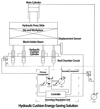
A proportional servo variable hydraulic motor is used as a primary regulating element to directly drive a proportional servo variable hydraulic pump as a secondary regulating element. The secondary regulating controller collects pressure signals from the hydraulic cushion cylinder and the main cylinder.
When the hydraulic press stretches the workpiece, the hydraulic cushion cylinder first raises to support the sheet metal. The main cylinder starts to descend and pressurize. When the upper die contacts the sheet metal and continues to press, the oil pressure in the hydraulic cushion cylinder passively rises. The discharged hydraulic oil drives the primary component hydraulic motor to rotate, and the hydraulic motor drives the secondary component hydraulic pump to rotate and discharge high-pressure hydraulic oil into the main cylinder.
When not considering factors such as efficiency, the torque function relationship of the secondary regulating loop should comply with the following formula:
p1·q1= p2·q2
Where: p1 - pressure of the hydraulic cushion cylinder; q1 - displacement of the secondary element hydraulic motor; p2 - pressure of the main cylinder; q2 - displacement of the secondary element hydraulic pump.
Our control objective is to keep p1 constant, or described as controlling p1 within the allowable accuracy range of the process to keep it stable.
From the above formula, it can be seen that adjusting q1 and q2 can achieve the goal of stabilizing p1. This control process is achieved by the secondary regulating controller shown in the diagram.
Key technologies of secondary regulation system:
Selection of primary component:
1. Determine the maximum operating pressure of the hydraulic cushion.
2. Determine the descent speed of the hydraulic cushion, calculate the oil discharge flow rate of the hydraulic cushion.
3. Select the rotation speed of the hydraulic motor, generally controlled within 1500-2500 rpm (depending on the component parameters), with the highest speed considering the rotation speed of the secondary component.
4. Select the type of hydraulic motor according to the operating pressure.
5. Calculate the displacement of the hydraulic motor based on the oil discharge flow rate of the hydraulic cushion and the maximum rotation speed of the selected hydraulic motor. It is advisable to choose a high-frequency response variable type hydraulic motor.
6. Calculate the maximum torque of the hydraulic motor.
Selection of secondary component:
1. Determine the maximum operating pressure of the master cylinder.
2. Use the maximum torque of the hydraulic motor as the input torque of the secondary component hydraulic pump, and calculate the pump displacement. It is advisable to choose a high-frequency response variable type hydraulic pump.
Control strategy:
1. Determine the hydraulic pressure for edge pressing, p1.
2. Detect the oil discharge volume of the hydraulic cushion cylinder or calculate Q1 from the pressing speed of the slide.
3. Estimate the motor speed and displacement q1, calculate the motor output torque T1, T1 = p1· q1.
4. Measure the pressure of the master cylinder, p2.
5. Pump input torque T2 = T1.
6. Calculate the pump displacement based on the input torque of the pump: T2 = p2· q2, q2 = T2 / p2.
7. Optimize q1 and q2; during the servo follow-up process, optimize q1 and q2 at any time when p2 changes to keep p1 constant.
5. Energy-saving advantages of secondary regulation technology
When the hydraulic cushion is passively pressed down, the hydraulic cushion cylinder continuously discharges high-pressure hydraulic oil. In conventional hydraulic systems, this high-pressure energy is consumed entirely by generating heat through the relief valve, and the hydraulic system still needs to be equipped with a cooler to cool the heated hydraulic oil through consuming energy again. However, with the use of secondary regulation technology, the high-pressure hydraulic energy discharged from the hydraulic cushion cylinder is all used to pressurize the main cylinder, eliminating the energy conversion efficiency loss between the motor and pump. Taking into account the reduced cooling energy consumption, the total energy saving efficiency should be around 60-70%. As secondary regulation technology and supporting components continue to mature, this technology will surely be widely applied.

XIRO-electric servo press/XIRO-hydraulic press/XIRO-mechanical powder compacting press
XIRO, an automated machine manufacturer, 24-hour response factory, with a professional engineering team 24 hours online technical service. All machines are CE certified, come with a 2-year warranty, and lifetime service. With 20+ years rich production experience, our equipment is exported to more than 60 countries. We provide customizable press machines and comprehensive productivity solutions, ensuring it's the most competitive, accurate solution to any assembly requirement! XIRO wishing you prosperity!
 |  |  |


