


PLC-Based Four-Column Hydraulic Press Control System
Four-column hydraulic presses are not only used in metallurgy, forging, machinery manufacturing, transportation, aerospace, and other fields, but also widely used in many sectors of the national economy, such as sheet metal forming, powder metallurgy, extrusion of profiles, plywood pressing, packaging, synthetic diamond production, carbon grade pressing, part assembly, straightening, etc.
The hydraulic control system of the four-column hydraulic press not only needs to have the requirements of pressure and speed being continuously adjusted within a wide range, flexible movements, and easy coordination between various executive mechanisms, but also needs to meet the requirements of work intensity, production efficiency, and automatic adjustment according to the desired pressure by the user.
Most traditional hydraulic press control systems are relay-contactor control systems, which are not easy to achieve automatic adjustment functions. At the same time, the hydraulic-electrical control circuit is relatively complicated, frequent failures occur during the production process, and troubleshooting and fault elimination are difficult. Additionally, with large-scale production, long operating times, severe component aging phenomena lead to a significant decrease in system stability and reliability.
On the other hand, PLC-based hydraulic-electrical control systems of hydraulic presses have high reliability, good flexibility, simple programming, easy use, easy troubleshooting, easy development, and easy implementation of automatic adjustment of pressure and time.
Now, let's learn more about the PLC-based four-column hydraulic press control system.
1. Structure and Function of Four-Column Hydraulic Press
The four-column hydraulic press mainly consists of four guide columns, a crossbeam, a worktable, an upper slide block, a lower slide block, and an ejection mechanism, as shown in the diagram.
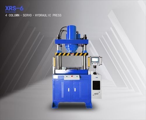
The XRS-6 downward four-column hydraulic press developed by XIRO Technology. This equipment adopts a cylinder-beam integrated design, with strong load-bearing capacity, compact structure, space-saving, and equipped with a master-slave cylinder structure. It can achieve rapid operation under no load, suitable for processing relatively small automotive parts, hardware tools, gears, and other parts.
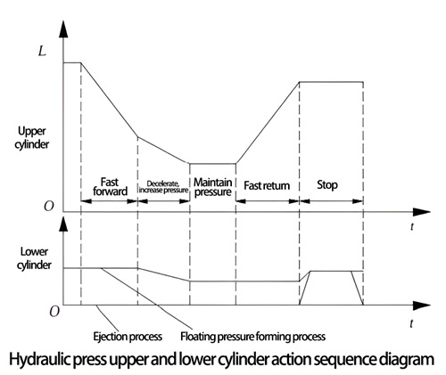
The main movements of the hydraulic press are the movements of the upper slide block mechanism and the lower slide block ejection mechanism. The upper slide block mechanism is driven by the main hydraulic cylinder (upper cylinder), and the ejection mechanism is driven by the auxiliary hydraulic cylinder (lower cylinder). The upper slide block mechanism of the hydraulic press is guided by four guide columns, driven by the main cylinder, to achieve the action cycle of "rapid descending → slow pressure increase → pressure holding delay → rapid return → stop in place." The lower cylinder is arranged in the middle hole of the worktable, driving the lower slide block ejection mechanism to achieve two action cycles of "upward ejection → downward retraction" or "floating edge pressing downward → stop → ejection." The sequence of movements of the upper and lower cylinders of the four-column hydraulic press is shown in Figure 2.
2. Working Principle of Hydraulic System
The hydraulic system of the four-column hydraulic press uses two variable pumps to provide pressure oil for the system. The main pump 1 is a high-pressure, large-flow constant power (pressure compensation) variable pump, with the maximum working pressure regulated by the remote pressure regulating valve 5 of the relief valve 4. The auxiliary pump 2 is a low-pressure, small-flow fixed-displacement pump used to supply control oil for the hydraulic valve, with its pressure adjusted by the relief valve 3. Figure 3 shows the hydraulic system diagram of the system. The sequence of actions of the solenoid valve coils in the entire hydraulic system diagram is shown in Table.

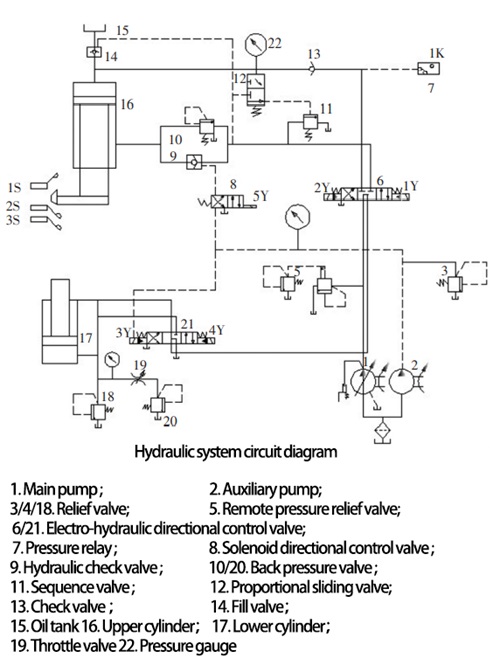
During the working process of the hydraulic control system, the main pump 1 can be started without load by the mid-position function of the electro-hydraulic directional valves 6 and 21. The main pump 1 unloads when the main and auxiliary hydraulic cylinders stop in their original positions.
1. Master cylinder movement
(1) Fast downward movement: When coil 1Y is energized, the pressure oil from the hydraulic pump passes through the directional valve 6 (right position), one-way valve 13, and enters the upper chamber of the master hydraulic cylinder 16. At the same time, the system utilizes the self-weight of the upper slider assembly to achieve the fast downward movement of the master hydraulic cylinder (upper cylinder), and oil is replenished using the filling valve 14. The return oil path for the fast downward movement of the upper cylinder is through the lower chamber of the upper cylinder, through the hydraulic one-way valve 9 (5Y energizes to open the hydraulic one-way valve), the right position of the electro-hydraulic directional valve 6, and the middle position of 21 back to the oil tank.
(2) Slow working advance: After the slider contacts the workpiece at slow speed, the resistance increases. At this time, the pressure in the upper chamber of the master cylinder 16 quickly rises. The hydraulic one-way valve 14 is closed, and only the hydraulic pump continues to provide high-pressure oil to the upper chamber of the master cylinder, pushing the piston to slowly descend and pressurize the workpiece. The speed of pressurization is determined only by the flow rate of the hydraulic pump, and the flow of oil is the same as that during fast downward movement.
(3) Oil pressure maintenance: After the upper cylinder drives the upper die and the lower die to close, the pressure oil continues to enter the upper chamber of the oil cylinder, and the pressure in the upper chamber continues to rise. Due to the increase in oil pressure, the hydraulic one-way valve at the filling tank is closed, cutting off the oil supply from the filling tank. The speed of descent of the upper cylinder 16 begins to slow down, and the pressure in the upper chamber of the oil cylinder continues to rise. When the pressure exceeds the setting value of pressure relay 7, the pressure relay sends a signal, the control electro-hydraulic directional valve 6 switches to the middle position, cutting off the oil supply to the upper chamber of cylinder 16, and the upper cylinder stops moving, and the system begins to maintain pressure.
(4) Pressure relief, fast return: After the pressure is maintained, coil 2Y of the electro-hydraulic directional valve 6 is energized (coil 1Y is de-energized) to the left position is turned on. The pressure oil pumped out by pump 1 passes through the left position of the electro-hydraulic directional valve 6, then through the back pressure valve 10, enters the lower chamber of the upper oil cylinder 16, pushing the oil cylinder upwards. At the same time, the return oil in the upper chamber of cylinder 16 passes through the hydraulic one-way valve 14, flowing back to the filling tank 15, allowing the upper cylinder to quickly return to its original position.
2. Top-out cylinder movement
(1) The action of the top-out cylinder 17 is carried out after the main cylinder stops moving. The solenoid of the electro-hydraulic directional valve 21 is energized (4Y de-energized), because the pressure oil entering the top-out cylinder must first pass through the neutral position of the main cylinder directional valve 6 (i.e. the position where the main cylinder stops moving), and then enter the directional valve 21 controlling the movement of the top-out cylinder, thus achieving the interlock of the main cylinder and the top-out cylinder movement; the pressure oil enters the lower chamber of cylinder 17 through the left position of 21, and the pressure oil in the upper chamber flows back to the oil tank through the left position of 21.
(2) The retracting action of the top-out cylinder occurs after the workpiece is removed, the solenoid of the electro-hydraulic directional valve 21 is energized (3Y de-energized), and the right position starts to work. Pressure oil enters the upper chamber of cylinder 17, and the return oil from the lower chamber flows into the return oil tank through the right position of the valve. The cylinder moves downward and returns to its original position.
(3) Both solenoids 3YA and 4YA of the top-out cylinder are de-energized, the electro-hydraulic directional valve 21 of the lower cylinder is in the neutral position, and the top-out cylinder stops moving.
Note: The hydraulic check valve 14 can prevent the flow of oil from the upper chamber of the upper oil cylinder 16 during pressure holding. The stroke switch is used to control the extreme positions of the upper and lower cylinders, and pressure gauges respectively indicate the pressure of the upper and lower oil cylinders and the entire system.
3. PLC Control System Design
Due to the fact that PLC can perform logic, sequence, timing, counting, and arithmetic operations, and its programming language is quite powerful, it also has a series of advantages such as loop scanning and real-time refreshing. Therefore, Mitsubishi control system is adopted to replace the original relay contactor control system, while maintaining the electromagnetic valve action sequence table and control requirements unchanged. According to the hydraulic system control requirements of the four-column hydraulic press, the system requires 9 input signals (X0-X10) and 6 output signals (Y0-Y5). In consideration of future system development, multiple spare points are reserved for input and output signals, so the FX2N-32MR is selected; the relay output form adopts ladder diagram programming mode. The process is carried out step by step, so it is very convenient to write the program according to the process flow chart. 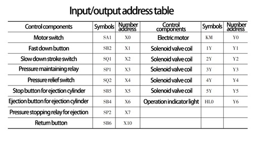
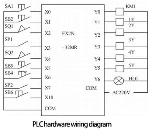
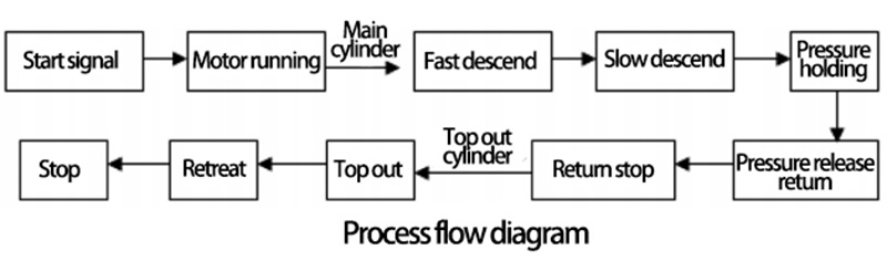
In the process of PLC control system design, the input-output address table is provided according to the design steps, as shown in Table. The PLC hardware wiring diagram, process flow chart, and PLC program design schematics are shown in the following figures.
The process flow of the four-column hydraulic press system reflects the entire system's operation process. The process flowchart clearly expresses the system's operating status. PLC using sequential programming method is very convenient, making it easy to debug programs and troubleshoot errors.
4. Conclusion
After the replacement of relay contactor control system with PLC, the hydraulic control system has undergone installation, debugging, improvement, and enhancement. The system not only meets the requirements of work intensity and production efficiency but also it is very easy to operate. It can achieve jog, semi-automatic, and fully automatic cycle actions. The working pressure and pressing speed of the system can be adjusted at any time within the stroke range as needed, and it can complete various process modes such as constant pressure and constant stroke. The transformed control system can be very flexible to set and adjust the pressure holding time and pressure as needed for the system. At the same time, the PLC hydraulic control system also avoids a series of shortcomings such as large machine tool vibration noise, oil leakage, etc. After being put into production, the entire system runs smoothly and reliably, greatly reducing the failure rate. The system efficiency is greatly improved, not only with good economic performance but also very simple and convenient maintenance.
Furthermore, the PLC control system has good flexibility, which adds flexibility for future system upgrades. Especially when customers need to change product processes according to production requirements, there is no need to redesign control system circuits and complex installation wiring. Just changing the user program can achieve the corresponding control requirements, greatly reducing the cumbersome wiring connections and workload, and shortening the system update cycle.

XIRO-electric servo press/XIRO-hydraulic press/XIRO-mechanical powder compacting press
XIRO, an automated machine manufacturer, 24-hour response factory, with a professional engineering team 24 hours online technical service. All machines are CE certified, come with a 2-year warranty, and lifetime service. With 20+ years rich production experience, our equipment is exported to more than 60 countries. We provide customizable press machines and comprehensive productivity solutions, ensuring it's the most competitive, accurate solution to any assembly requirement! XIRO wishing you prosperity!
 |  |  |


