


 +86 15913754357
 sales@xirotech.cn
 Release time:2024.08.01
A hydraulic press uses hydraulic technology to transmit energy with liquid as the working medium, thereby achieving various forging and forming processes. Traditional hydraulic presses operate using asynchronous motors and control is achieved through proportional servo valves or proportional pumps. However, they have many drawbacks, such as high noise, high energy consumption, low production efficiency, low precision, and the inability to achieve precise speed regulation. With the rapid development of motor and digital technologies, more and more intelligent technologies are being applied to the design of hydraulic press systems, significantly increasing the intelligence of hydraulic presses.
The author has designed an electro-hydraulic system for a hydraulic press based on AC servo technology and digital technology. Taking into account the actual working characteristics of the hydraulic press, a hardware system scheme for the electro-hydraulic system was designed. In addition, software algorithms were studied to meet practical operational needs, and a software flowchart was provided. This system design allows for real-time adjustment of the pressing speed of the hydraulic press according to customer requirements, improving the operational precision and automation of the hydraulic press.
1. Composition and Working Principle of Hydraulic System
1.1 Composition of Hydraulic System
A hydraulic system consists of five parts: power components, actuating components, control components, auxiliary components, and working medium.
-
Power Components: These are the most important parts of the hydraulic transmission system, responsible for energy conversion, primarily converting mechanical energy into pressure energy.
-
Actuating Components: Generally, these are hydraulic motors or cylinders that convert the pressure energy of the oil into mechanical energy.
-
Control Components: These consist of various control valves that regulate the direction, pressure, and flow rate of the hydraulic oil in the hydraulic transmission system.
-
Auxiliary Components: These mainly support various control functions in the hydraulic transmission system, including elements like pressure gauges and oil filters.
-
Working Medium: This primarily refers to the hydraulic oil required for the operation of the hydraulic transmission system, mainly providing energy conversion for the oil pump and hydraulic machine.
1.2 Working Principle
Hydraulic systems are widely used in various fields of mechanical equipment, and the selection of hydraulic oil is very important, generally requiring continuous flow. The specific working principle of a hydraulic system is as follows: The hydraulic pump converts the mechanical energy generated by the prime mover into the pressure energy of the oil. Under the action of various control valves, the oil is pressurized and sent to the actuators of the hydraulic motor or hydraulic cylinder, where it is finally converted into mechanical energy to drive the load. The load is then pushed to perform pressing work under the drive of mechanical energy.
Based on the traditional working principle, this design selects a mechanical hydraulic system combining a fixed displacement pump and a hydraulic cylinder to control the hydraulic press and drive the load to work.
2. Overall Design of the Electro-Hydraulic System
This electro-hydraulic system design for the hydraulic press integrates mechanical hydraulic transmission technology, AC servo technology, sensor measurement technology, and PLC control technology. Additionally, a supervisory control system for the host computer is designed. AC servo technology and a fixed displacement pump are used as the energy sources to control the hydraulic system. Sensors are employed for online detection of operating parameters of each system. The PLC serves as the main controller for processing and analyzing real-time data, while PC monitoring software is used to set and monitor the system's operating conditions. The overall design scheme of the servo hydraulic press's electro-hydraulic system is shown in Figure 1.
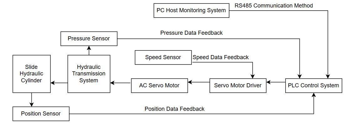
Figure 1: Overall design scheme of the servo hydraulic press electro-hydraulic system
3. Design of Electrical Control System
3.1 Selection of PLC Controller
The PLC (Programmable Logic Controller) is a microcomputer designed specifically for industrial environments to implement control functions. It is characterized by strong anti-interference capabilities, high reliability, and short development cycles. Based on these advantages, the design chooses the Siemens S7-200 PLC as the main controller to achieve data analysis, processing, and control of the electro-hydraulic system of the hydraulic press.
3.2 Servo Motor Circuit Design
A servo motor is a new type of motor fully controlled by control signals, employing closed-loop control of position, which fundamentally resolves the issue of step loss in stepper motors, greatly enhancing the production efficiency and precision of industrial automation systems. However, AC servo motors cannot operate independently and usually require a dedicated driver.
This design opts for an AC servo motor to replace the conventional motor used in traditional hydraulic presses, driving a fixed displacement pump to control the sliding hydraulic cylinder. The electrical connections between the AC servo motor driver and the motor are shown in Figure 2.
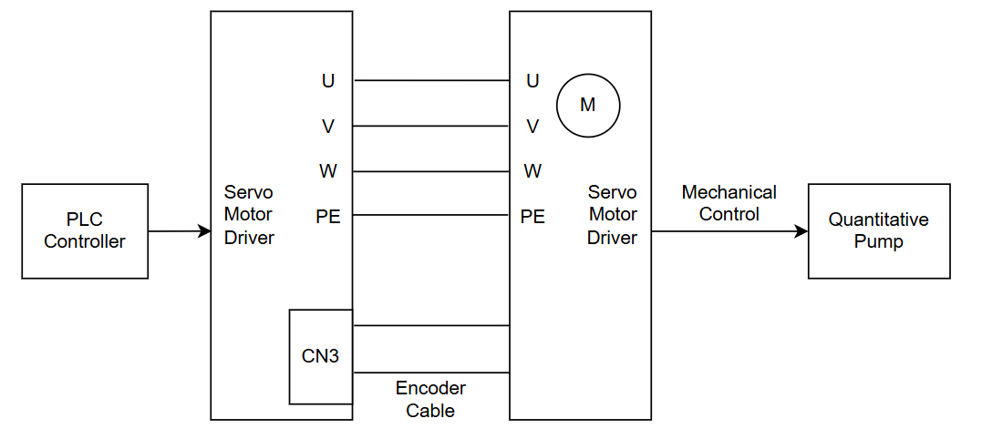
Figure 2: Electrical Wiring Diagram of AC Servo Motor Driver and Motor
By connecting the driver to the AC servo motor to form a servo motor system, and combining control from the host computer and the PLC controller, different speeds of the servo motor are realized. This, in turn, drives the fixed displacement pump to achieve different flow rates and working pressures in the hydraulic system, thereby achieving breakthroughs in intelligent variable speed and high-precision operation of the hydraulic press.
3.3 Sensor Analog Input Circuit
To achieve the goal of intelligent speed-regulated stamping for the system, this design uses sensor detection technology. A pressure sensor is used to measure the pressure in the hydraulic system, a speed sensor to measure the rotational speed of the AC servo motor, and a displacement sensor to detect the displacement of the hydraulic cylinder slider. The collected data is transmitted to the PLC data acquisition system, facilitating intelligent regulation of the system. The sensors used in this design all output analog signals. Since the PLC does not have the capability to collect analog signals, an analog acquisition module is used to convert the sensor data into a format that can be connected to the PLC. The connection diagram is shown in Figure 3. It only requires connecting the signal lines and the negative power terminals of each sensor to the analog acquisition module. The analog acquisition module is connected to the PLC via an RS 485 communication circuit.
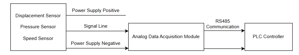
Figure 3: Sensor Input Circuit Diagram
This design employs the Siemens EM 231 analog acquisition module to convert data from the three types of sensors. The four-channel external analog inputs can be converted into twelve-bit digital quantities required for internal processing by the PLC controller.
3.4 RS485 Communication Circuit Design
In the designed electro-hydraulic control system of the hydraulic press, data transmission among the sensor measurement system, PC computer terminal, servo motor system, and PLC controller is achieved through RS 485 communication. The RS485 communication method is a relatively economical choice, as its communication cable costs are comparatively low.
To ensure the stability of data transmission in the electro-hydraulic control system of the hydraulic press, an isolated RS 485 communication circuit is used, as shown in Figure 4.
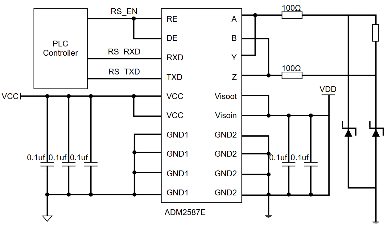
Figure 4: RS485 Bus Circuit
During the circuit design process, the ADM2587E single-supply isolation chip from Analog Devices Inc. (ADI) was selected. This circuit isolates the system power supply from the RS 485 transceiver power supply through DC-DC conversion, which can completely eliminate the influence of common-mode voltage.
4. Software Process Design
4.1 Software Design Approach
The designed hydraulic press can achieve both manual and automatic operation. The automatic operation function utilizes AC servo technology, allowing the hydraulic press to change speed through control commands set on the upper computer. To enhance the system control precision, PID regulation technology is used to perform real-time control of the electro-hydraulic system's operation. Real-time online measurement of motor speed, hydraulic cylinder position, and hydraulic system pressure is conducted using sensor detection technology, forming a closed-loop feedback control with the set values. The system's closed-loop feedback diagram is shown in Figure 5.
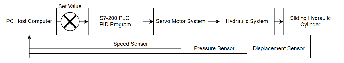
Figure 5: System Closed-Loop Feedback Control Block Diagram
4.2 Software Flowchart Design
The system software section consists of two parts: one is the program design for the lower machine controller, and the other is the software design for the upper machine monitoring system. The upper machine monitoring system uses the Kingview software, which has a good human-machine interface and simple programming. After secondary development of this software, a detection system specifically for hydraulic machines is formed. The lower machine program section uses the STEP7 Microwin programming software, which is specifically developed for the S7-200 PLC controller and can run perfectly on Windows.
Based on the concept of modular program design, the PLC control program design includes a main program and various modular auxiliary programs, each running separately using an interrupt method. The modular programs are shown in Figure 6.
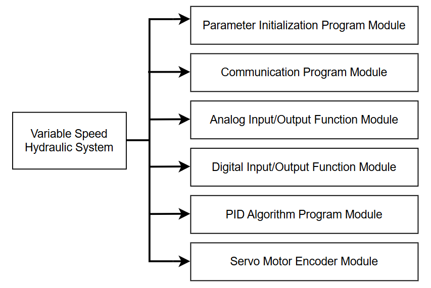
Figure 6: Modular Program Functions
After powering on the variable-speed hydraulic press's electro-hydraulic system, the PC upper-level software sends a control command to the PLC controller according to the customer's requirements. The PLC controller outputs a certain voltage to control the servo motor driver. When the driver receives the system's output voltage, it controls the servo motor's speed, which in turn adjusts the displacement pump speed, achieving variable speed control of the hydraulic press's downward speed. At the same time, the controller collects and processes data such as the system's speed, displacement, and pressure, comparing these with the system's set values to improve control accuracy. The system control software flow is shown in Figure 7.
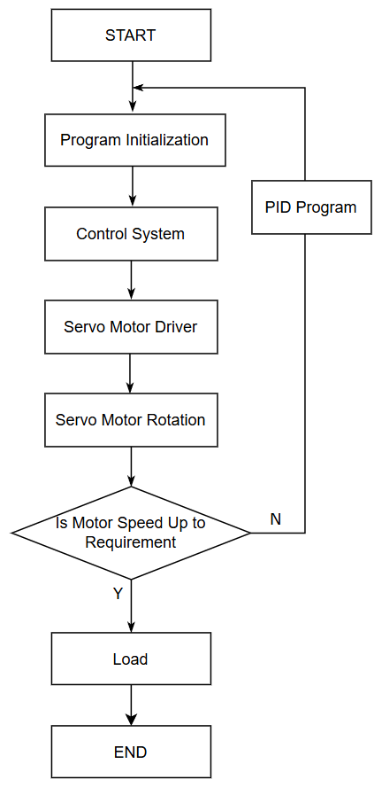
Figure 7: System Software Control Program Flowchart
5. Application Effect
The designed electro-hydraulic system was applied to a prototype with a nominal force of 16 tons. After testing, all the indicator parameters of the prototype met the design values. During operation, the prototype produced minimal noise. Under the control of the servo motor, the hydraulic press exhibited almost no idle energy consumption, demonstrating excellent application performance. Table 1 shows the parameter indicators of the prototype during operation.
Table 1: Parameter Indicators of the Prototype During Operation
| PROJECT |
VALUE |
|
Nominal force of prototype (t) |
160 |
|
Slider quick descent speed (mm/s) |
450 |
|
Working speed (mm/s) |
0-40 |
|
Energy consumption reduction (%) |
30 |
|
Error precision (mm) |
±0.1 |
Based on the analysis of many defects in traditional ordinary hydraulic presses, and considering the current requirements for speed and precision in hydraulic presses, a new electro-hydraulic system design scheme for hydraulic presses is proposed. Through the design of the system's hardware and software, intelligent speed control of the hydraulic press has been achieved. Experimental prototypes show that this design meets the expected goals, with good control effects, low energy consumption, and excellent engineering application results, providing a new solution for hydraulic press manufacturing technology.

1.What is a hydraulic system?· XIRO (xiromachinery.com)

XIRO-electric servo press/XIRO-hydraulic press/XIRO-mechanical powder compacting press
XIRO, an automated machine manufacturer, 24-hour response factory, with a professional engineering team 24 hours online technical service. All machines are CE certified, come with a 2-year warranty, and lifetime service. With 20+ years rich production experience, our equipment is exported to more than 60 countries. We provide customizable press machines and comprehensive productivity solutions, ensuring it's the most competitive, accurate solution to any assembly requirement! XIRO wishing you prosperity!

|

|

|

