Check valves are classified into two types: the standard check valve and the pilot-operated check valve. The standard check valve, often simply referred to as a check valve, allows oil to flow in only one direction while preventing reverse flow. Therefore, it is also known as a non-return valve or a backflow prevention valve.
The pilot-operated check valve is a type of valve that allows bidirectional oil flow once control pressure oil is introduced. It consists of two parts: the check valve and a pilot control mechanism. When the control port is not supplied with pressure oil, it functions the same as a standard check valve, permitting forward flow while blocking reverse flow. When pressure oil (also called control oil) is introduced into the control port, the control piston pushes the conical valve spool away from the valve seat, allowing oil to flow in both directions.
1. Structure, Working Principle, and Classification of the Pilot-Operated Check Valve
1.1 Structure and Classification of the Pilot-Operated Check Valve
The pilot-operated check valve consists of a valve body, control piston, valve spool, and a spring. Based on the way oil leakage is handled, pilot-operated check valves can be classified into internally drained and externally drained types, as shown in Figures 1 and 2. The externally drained pilot-operated check valve can further be divided into two structures: with a small unloading valve spool and without one.
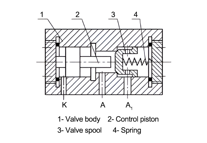
Figure 1: Internally drained pilot-operated check valve
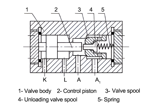
Figure 2: Externally drained pilot-operated check valve
1.2 Working Principle of the Pilot-Operated Check Valve
Figure 1 shows a schematic diagram of the internally drained pilot-operated check valve. When no pressure oil is introduced into the control port K, oil entering from port A pushes the valve spool against the spring, allowing oil to flow out from port A1. Conversely, when oil enters from port A1, the spring forces the valve spool to tightly seal against the valve seat, preventing oil from flowing through.
At this point, the pilot-operated check valve functions as a standard check valve. When pressure oil is introduced into the control port K, the control piston pushes the valve spool away from the valve seat, allowing oil to flow in both directions.
When oil flows in the reverse direction, i.e., entering from port A1, the inlet pressure is equivalent to the system's working pressure, which is usually high. Sometimes the pressure at port A is also high, creating significant backpressure when the control piston moves. The pressure of the oil at the control port must be sufficiently high to open the conical valve spool. This not only leads to energy loss but also affects the reliability of the pilot-operated check valve's operation. Therefore, internally drained pilot-operated check valves are mainly used in situations where there is no backpressure, or very little backpressure, in the reverse flow chamber.
When the inlet pressure at port A is high, it creates large backpressure when the control piston moves. In such cases, an externally drained valve can be used to reduce the backpressure. Figure 2 shows an externally drained pilot-operated check valve with an unloading valve spool. The control piston and valve body are designed with two concentric sections. When the pressure at port A is high, the area affected by backpressure on the control piston is small, reducing resistance when the control piston pushes open the valve spool. The drain port L returns the leakage oil from chambers A and K to the oil tank, effectively eliminating resistance. Externally drained pilot-operated check valves are primarily used in situations where the backpressure at the reverse oil outlet (port A) is high, allowing for a reduction in minimum control pressure and minimizing control power.
When oil flows in the reverse direction and the inlet pressure at port A1 is high, the resistance when using the control piston to push open the conical valve spool is significant, making it difficult to open the valve spool. In such cases, an unloading valve spool (as shown in Figure 2) can be used. The unloading valve spool is a smaller valve spool installed inside the conical valve spool of the pilot-operated check valve and is referred to as a pilot valve spool or unloading valve spool. Due to its smaller area, the force acting on it is relatively low. Therefore, even when the control oil pressure is not very high, the control piston can push open the unloading valve spool. At this point, ports A and A1 are connected through the small orifice in the unloading valve spool, gradually releasing the pressure from port A1 until the control piston pushes the main valve spool away from the valve seat, allowing reverse oil flow.
2. Rational Application of Pilot-Operated Check Valves
In hydraulic systems, pilot-operated check valves are also known as "hydraulic locks." Due to their excellent locking capability, leak-proof design, and ability to maintain the locking position of hydraulic cylinders for extended periods, they are commonly used in balance circuits, pressure-holding circuits, and locking circuits, such as the outrigger circuits of hydraulic cranes.
2.1 Balance Circuit
To prevent vertical hydraulic cylinders and their working components from slipping due to their own weight when stopped in a suspended position, or to avoid uncontrolled overspeed during downward motion, a balance circuit can be set up.
Although pilot-operated check valves have excellent sealing performance and can lock the piston and working components of a hydraulic cylinder in position, they do not guarantee a stable speed during the downward movement of the working components. Therefore, a one-way throttle valve can be added in the return oil path to form a balance circuit, as shown in Figure 3. The role of the one-way throttle valve is to provide an oil supply path to the rodless chamber when the working component rises and to restrict the flow when it descends, preventing uncontrolled overspeed.
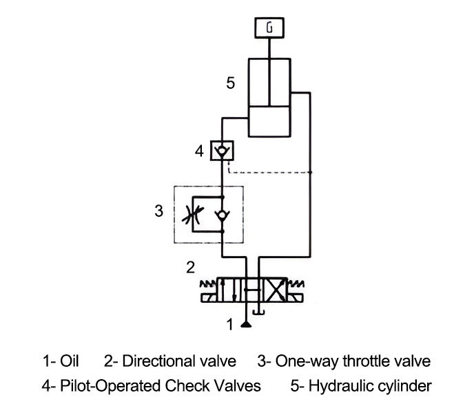
Figure 3: Balance circuit
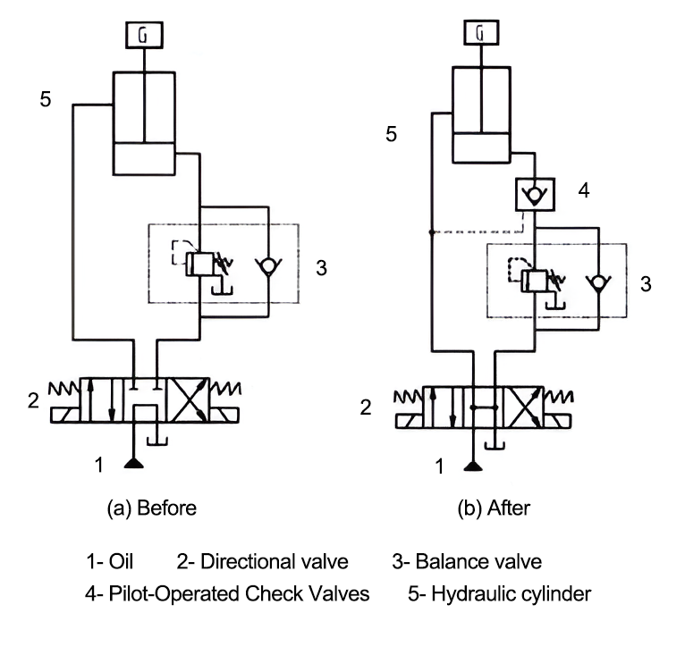
Figure 4 Balancing circuit
Figure 4(a) shows a balance circuit composed of a one-way sequence valve, where the sequence valve functions as a balance valve. This circuit uses an M-type directional valve. When the hydraulic cylinder stops working, the oil in both the upper and lower chambers of the cylinder is sealed, helping to lock the working components and allowing the pump to unload, thus reducing energy consumption.
In such balance circuits, there may be leakage in the sequence valve, causing the working components to slowly descend over time. Therefore, a pilot-operated check valve can be added between the hydraulic cylinder and the sequence valve to reduce leakage and improve locking precision, as shown in Figure 4(b). To keep the working components locked when suspended, the M-type center position of the directional valve should not be used. Otherwise, the control oil of the pilot-operated check valve will not be unloaded in time, and the lock cannot be applied immediately.
2.2 Filling Circuit
Figure 5 shows a filling circuit for a vertical hydraulic cylinder. When the piston descends, its own weight, the weight of the oil, and the weight of the working mechanism cause the piston to accelerate downward. The supply of oil to the rodless chamber may be insufficient, causing the pressure of the oil in that chamber to drop rapidly, or even become negative, leading to cavitation as bubbles form in the oil, creating noise. The presence of negative pressure may also cause the working mechanism to slow down or even stop. A filling device must be added in this case. The pilot-operated check valve in Figure 5 serves the function of filling and replenishing oil.
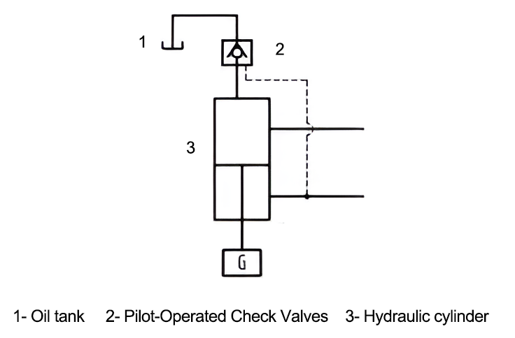
Figure 5: Filling circuit
2.3 Large-Flow Oil Discharge Circuit
For double-acting single-rod hydraulic cylinders, the areas of the two oil chambers are quite different, resulting in unequal oil supply and return volumes. When oil is supplied to the rod chamber, the return flow from the rodless chamber is large. If a sliding spool directional valve with a low rated flow is used, it can create significant backpressure between the rodless chamber and the tank, causing throttling effects. This leads to unnecessary pressure losses and reduces the retraction speed of the piston rod. If a pilot-operated check valve is used, as shown in Figure 6, the oil pressure in the inlet path opens the conical valve spool through the control piston, allowing the oil to flow back to the tank via the pilot-operated check valve.
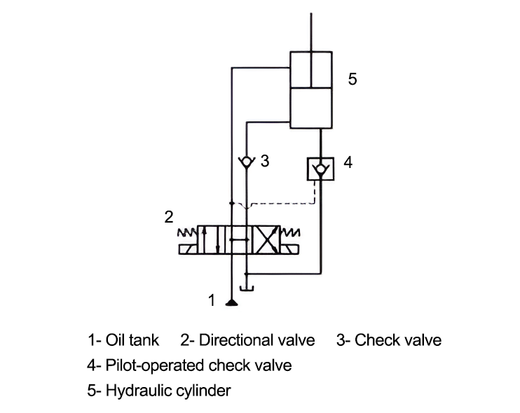
Figure 6: Large-Flow Oil Discharge Circuit
Some hydraulic equipment requires the hydraulic actuator to maintain pressure for a certain period when it stops during its stroke to prevent deformation or rebound of the processed workpiece. In such cases, a pressure-holding circuit is necessary. A pressure-holding circuit maintains stable, constant pressure when the actuator stops working or when there is a slight displacement due to workpiece deformation.
There are various methods for designing pressure-holding circuits. A fixed-displacement pump can be used to achieve pressure holding, but the hydraulic pump must operate under high pressure, and almost all the pressurized oil flows back to the tank via the relief valve, resulting in significant power loss and heating of the oil. Therefore, this type of circuit is only suitable for small hydraulic systems with short pressure-holding times. If a sliding spool solenoid directional valve is used for pressure holding, the inherent leakage in the spool design makes it suitable only for short pressure-holding durations.
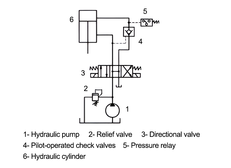
Figure 7: Pressure-Holding Circuit
Figure 7 shows a pressure-holding circuit using a pilot-operated check valve. Since the valve spool in the pilot-operated check valve is conical, leakage is minimal, and the sealing performance is excellent, providing a good pressure-holding effect. When oil enters the rodless chamber and the piston rod extends to the predetermined position, the pressure in the inlet chamber rises. When the pressure reaches the set value, the pressure relay sends a signal, the solenoid directional valve returns to the H-type center position, the hydraulic pump unloads, and the pilot-operated check valve closes, holding the pressure in the rodless chamber. When the pressure in the rodless chamber drops below the lower limit set by the pressure relay, the pressure relay sends another signal, energizing the right-side solenoid, which shifts the directional valve to the right position. The hydraulic pump supplies oil to the rodless chamber again until the set value is reached, continuing the pressure-holding operation. Using a pilot-operated check valve not only enables long-term pressure holding but also allows the pump to unload, saving power.
3. Precautions for Use
3.1 Selection of the Mid-Position Function of the Directional Valve in the Circuit
In circuits using pilot-operated check valves, such as balance or pressure-holding circuits, it is necessary for the locking mechanism to be released when the actuator is operating, keeping the working oil ports interconnected, and maintaining a certain level of pressure at the control oil port. When the actuator is not in operation, the working oil ports of the pilot-operated check valve should be closed. Additionally, the control oil port should return to the oil tank when not in use; otherwise, the control piston may not reset properly, causing the check valve to fail in blocking reverse oil flow and preventing the lock from engaging.
When the directional valve is in the H-type (or Y-type) mid-position, the oil in the control port flows directly back to the tank, and no pressure builds up in the oil (except for pipeline pressure losses). At this point, the control piston resets due to the spring force, and the pilot-operated check valve remains in a locked state. However, if the mid-position function of the directional valve uses the O-type or another configuration, the pressure oil in the control chamber that controls the pilot-operated check valve may be trapped when the directional valve is in the mid-position and locking is required. In such cases, even when the check valve is closed, its control port may maintain a relatively high pressure for a certain period, preventing the check valve from locking quickly. Therefore, in hydraulic systems with pilot-operated check valves, it is not recommended to use O-type or M-type mid-position configurations for three-position directional valves, as they do not allow the check valve to close immediately. Instead, H-type or Y-type mid-position functions should be selected.
3.2 Properly Determine the Rated Flow of the Pilot-Operated Check Valve
In circuits composed of pilot-operated check valves and double-acting single-rod hydraulic cylinders, where the areas of the two oil chambers differ, sometimes significantly, the rated flow of the check valve must be carefully considered. The rated flow of the check valve should be determined based on the flow rate in the rodless chamber’s oil path. Otherwise, if the rated flow is insufficient, it may cause noise, such as squealing, when oil flows through the pilot-operated check valve in the rodless chamber.
3.3 Maintain Oil Cleanliness
When the filtration precision of the oil is insufficient or the oil quality is poor, contaminants in the oil can cause the valve spool or control piston inside the pilot-operated check valve to seize, leading to issues such as the valve failing to lock or unlock. This can affect the functionality of the system. The solution is to regularly clean the filter and replace the oil.
Pilot-operated check valves have significant value in various hydraulic circuits. When designing circuits, selecting pilot-operated check valves, and conducting related technical research, it is important to consider the purpose of the hydraulic circuit, the structural principles of the check valve, the drainage method, and the intended functions.
Additionally, attention should be given to the selection of the mid-position function of the directional valve in the circuit.
Finally, ensure that the rated flow of the pilot-operated check valve is correctly determined, and regularly maintain the oil quality.

1.What is a hydraulic system?· XIRO (xiromachinery.com)

XIRO-electric servo press/XIRO-hydraulic press/XIRO-mechanical powder compacting press
XIRO, an automated machine manufacturer, 24-hour response factory, with a professional engineering team 24 hours online technical service. All machines are CE certified, come with a 2-year warranty, and lifetime service. With 20+ years rich production experience, our equipment is exported to more than 60 countries. We provide customizable press machines and comprehensive productivity solutions, ensuring it's the most competitive, accurate solution to any assembly requirement! XIRO wishing you prosperity!
 |  |  |

