Hydraulic transmission technology has been widely applied across various industries, from light and heavy industries to high-precision fields in national defense. With its unique advantages, it has become indispensable in many areas.
Hydraulic systems are characterized by several advantages, such as compact size, light weight, compact structure, smooth operation, and the ability to achieve stepless speed regulation. However, hydraulic transmission also has certain disadvantages due to its unique nature: since hydraulic transmission uses liquid as a working medium, leakage between relatively moving surfaces is inevitable, and energy loss is relatively high during operation. With the trend towards higher pressure, speed, efficiency, and flow rates, improving the efficiency of hydraulic transmission systems has become a critical design consideration. In this article, we discuss several key aspects that should be considered to improve the efficiency of hydraulic systems.
1. Selecting Suitable Power Components
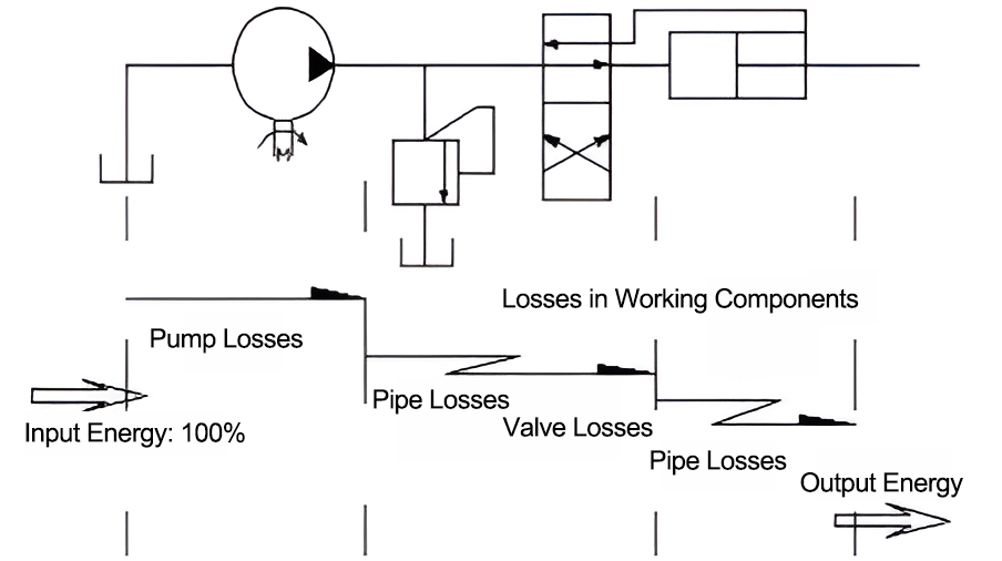
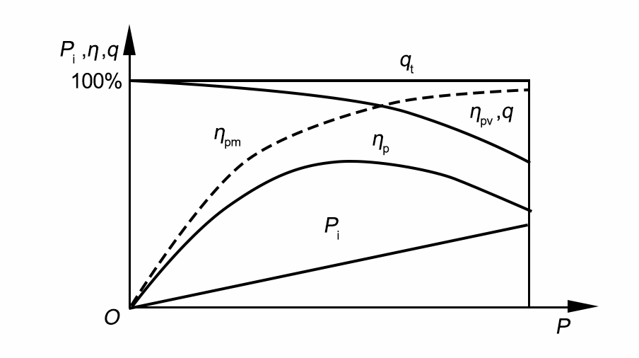
Energy distribution in a hydraulic system is shown in Figure 1. Without considering pressure losses, the total efficiency of the hydraulic pump ηp is the product of its volumetric efficiency ηpv and mechanical efficiency ηpm . The total efficiency ηp , volumetric efficiency ηpv , and mechanical efficiency ηpm can be experimentally determined. Figure 2 shows the relationship between the hydraulic pump’s total efficiency ηp , volumetric efficiency ηpv , mechanical efficiency ηpm , theoretical flow rate qt, actual flow rate q, actual input power Pi , and operating pressure P, under specific conditions such as medium, speed, and temperature.

Figure 1: Energy Distribution Diagram in a Hydraulic System

Figure 2: Performance Curve of the Hydraulic Pump
From the figure, it is clear that at zero pressure, the flow rate equals qt . As the pump’s operating pressure increases, leakage also increases, causing the volumetric efficiency ηpv and actual flow rate q to decrease. At zero pressure, the volumetric efficiency ηpv is 100%, meaning the actual flow q equals the theoretical flow qt . The total efficiency ηp rises rapidly as pressure increases, reaching its peak near the pump’s rated pressure before gradually decreasing again. Based on the changes in the volumetric efficiency ηpv and total efficiency ηp, we can infer the behavior of the mechanical efficiency ηpm . At low pressures, mechanical friction losses account for a significant portion of the total losses, resulting in low mechanical efficiency ηpm . As pressure increases, mechanical efficiency also rises quickly, remaining stable after reaching a certain value. Therefore, it is essential to choose the right pump type based on the load conditions to ensure it operates at a high efficiency. Generally, gear pumps are used for pressures below 2.5 MPa, vane pumps for pressures between 2.5 MPa and 6.3 MPa, and piston pumps for pressures above 6.3 MPa. Screw pumps are commonly used in low-pressure systems such as precision machine tools, food processing, and textile machinery. Additionally, the pump’s speed significantly affects its operating efficiency. Numerous engineering practices and test results indicate that the best operating efficiency is achieved at speeds between 1000 and 1900 rpm.
2. Selecting Suitable Control Components
Hydraulic systems are equipped with control components, primarily hydraulic valves. The energy loss in a hydraulic system mainly occurs due to the resistance loss in valves. As oil circulates through the system, significant energy is lost due to pressure drops, particularly in the main control valve. If hydraulic valves are selected based on the actual functional requirements of the system, pressure losses can be significantly reduced, thereby improving system efficiency. Improving the total efficiency of hydraulic valves primarily involves increasing their volumetric efficiency and pressure efficiency.
Extensive engineering practice and experimental data show that the internal pressure loss of hydraulic valves is closely related to their rated flow. When the actual flow through the valve is lower than the rated flow, the internal pressure loss is effectively controlled, and the pressure efficiency is consequently improved.
3. Selecting Suitable Actuators
The two types of actuators in hydraulic systems are hydraulic motors and hydraulic cylinders. When selecting a hydraulic motor, it is important not to reduce the motor's capacity specifications and to improve its volumetric efficiency. For actuators, mechanical efficiency is more important than volumetric efficiency. However, if the motor speed is too low and the pressure differential is large, the volumetric efficiency will decrease, which in turn reduces the overall efficiency. Generally, motor speeds of 1000 to 1800 rpm are recommended. For hydraulic cylinders, improving sealing conditions is essential. When designing cylinders, low-friction materials should be selected. For standard hydraulic cylinders, the energy-saving effect may not be very significant. However, for applications where operations alternate between fast and slow, designing new composite cylinders can achieve various levels of energy savings.
4. Reducing Internal Pressure Losses in Hydraulic Systems
When oil flows through pipelines and hydraulic components, pressure loss occurs. This pressure loss can be classified into two types: along the length of the pipeline (friction loss) and localized pressure loss. Friction loss occurs when oil flows through long, straight pipelines and is relatively minor. Localized pressure loss, on the other hand, is more significant and occurs when oil flows through valve bodies, bends, or pipe fittings. Therefore, reducing pressure loss in the system is an effective way to improve the working efficiency of hydraulic systems.
4.1 Reducing the Flow Speed of Oil Inside Hydraulic Pipelines
It is generally considered reasonable for the flow speed inside pressure oil pipelines to be between 2.8 and 6.2 m/s, and for suction pipelines, between 0.8 and 1.3 m/s. If the oil viscosity is high, the pipeline distance is long, and internal pressure is low, then the lower range of these values should be selected. Conversely, the higher values should be used.
4.2 Reducing Local Resistance and the Number of Control Valves
When oil flows through valve bodies, bends, pipe fittings, or areas where the cross-sectional area changes suddenly, it generates turbulence and localized pressure loss. During the initial design of hydraulic pipelines, the number of bends, diameter changes, and valves should be minimized. The inner walls of the pipes should be as smooth as possible to reduce frictional losses. During valve operation, a pressure differential exists between the inlet and outlet ports. The larger the pressure differential, the greater the localized loss. Therefore, the pressure differential and the number of valves should be minimized as much as possible. Using appropriately sized pipeline diameters can also help keep the flow velocity lower, reducing pressure loss throughout the system during operation.
4.3 Selecting the Appropriate Hydraulic Oil Viscosity
As the working medium, hydraulic oil is not only the energy carrier but also an indispensable part of the hydraulic system. It effectively cushions collisions and friction between various components during operation, ensuring the smooth functioning of the system. Hydraulic oil is subjected to complex forces such as friction, shear, and impact. If its viscosity is too high or too low, the system’s efficiency will be negatively affected. Therefore, selecting the appropriate viscosity and high-performance hydraulic oil based on the system’s operating pressure and ambient temperature is another effective way to improve the efficiency of the hydraulic transmission system.
5. Choosing the Appropriate Low-Energy Circuit
The hydraulic transmission system of any mechanical equipment is composed of several basic circuits. These are the fundamental building blocks of the hydraulic system. Selecting the right hydraulic circuit can significantly improve efficiency and reduce energy consumption.
5.1 Unloading Circuit
An unloading circuit allows the hydraulic pump to operate at near-zero pressure, reducing power loss and system heating, while extending the lifespan of the hydraulic pump and motor.

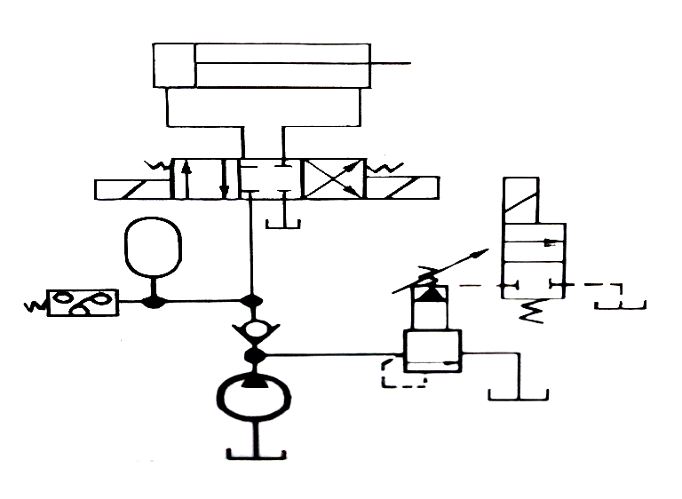
Figure 3: Unloading Circuit
(1)Unloading Circuit with a Solenoid Relief Valve: As shown in Figure 3, when the two-position, two-way solenoid directional valve in the solenoid relief valve is energized, the remote control port of the relief valve connects to the oil tank, causing the relief valve to open and the hydraulic pump to unload. This circuit also uses a hydraulic accumulator to maintain pressure when the hydraulic pump is unloaded. The working principle is that when the left position of the main directional valve is engaged, the cylinder moves right to perform clamping. Once the pressure reaches the set value, the pressure relay sends a signal, energizing the two-position, two-way solenoid directional valve, causing the hydraulic pump to unload, while the cylinder is kept under pressure by the hydraulic accumulator. This circuit is simple and energy-efficient.
(2)Unloading Circuit with a Three-Position Directional Valve: When the three-position, four-way M-type directional valve is in the mid-position, the hydraulic pump unloads. This circuit also utilizes a pilot-operated check valve to achieve automatic pressure maintenance.
5.2 Balance Circuit
A balance circuit is commonly used to prevent vertical cylinders and their working components from falling due to their own weight or losing control during downward movement. Typically, balance control is achieved using a balance valve and a pilot-operated check valve. Compared to using a pilot-operated check valve for balance control, a balance circuit with a balance valve operates independently of the backpressure in the hydraulic cylinder. It generally requires only 30% to 40% of the system pressure to open the balance valve. As the piston moves downward, the balance valve is opened by control oil, eliminating backpressure and improving system efficiency.
5.3 Throttle Speed Control Circuit
Throttle speed control circuits are commonly used in small power speed control systems. These circuits consist of a fixed displacement pump and a flow control valve, which adjusts the flow rate entering or exiting the actuator by controlling the flow area of the valve. This, in turn, regulates the speed of the actuator. There are three types of throttle speed control circuits: inlet throttle control, outlet throttle control, and bypass throttle control. Based on power characteristics analysis, bypass throttle speed control is more efficient because the output pressure of the hydraulic pump matches the load, and there is no pressure loss. Therefore, this circuit is more efficient in variable load and high-speed applications.
5.4 Volumetric Speed Control Circuit
Volumetric speed control circuits are commonly used in high-power speed control systems. These circuits adjust the speed of actuators by varying the displacement of a variable pump or a variable motor. In a volumetric speed control circuit, all the hydraulic oil output by the hydraulic pump flows directly into the hydraulic cylinder or hydraulic motor, with no losses from relief valves or throttling. Additionally, the pump’s working pressure varies with the load. As a result, this type of speed control circuit is highly efficient, generates little heat, and maintains high efficiency.
In summary, improving the efficiency of hydraulic systems involves minimizing flow and pressure losses. This requires careful consideration of every element, from power components, control elements, and actuators to pipeline design. By selecting the most efficient hydraulic circuits for specific needs, power losses can be minimized.

1.What is a hydraulic system?· XIRO (xiromachinery.com)
XIRO-electric servo press/XIRO-hydraulic press/XIRO-mechanical powder compacting press
XIRO, an automated machine manufacturer, 24-hour response factory, with a professional engineering team 24 hours online technical service. All machines are CE certified, come with a 2-year warranty, and lifetime service. With 20+ years rich production experience, our equipment is exported to more than 60 countries. We provide customizable press machines and comprehensive productivity solutions, ensuring it's the most competitive, accurate solution to any assembly requirement! XIRO wishing you prosperity!


